Download
1 / 19
210 likes | 253 Vues
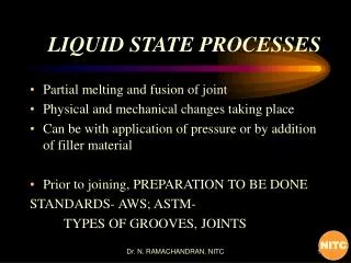
Lecture 25: The Liquid State Nucleation and Metallic Glasses. PHYS 430/603 material Laszlo Takacs UMBC Department of Physics. The states of matter. Gas - relatively simple

E N D
Lecture 25: The Liquid State Nucleation and Metallic Glasses PHYS 430/603 material Laszlo Takacs UMBC Department of Physics
The states of matter • Gas - relatively simple There is a reference state, the ideal gas, that can be understood in significant detail. “Real gases” are usually described as deviations from the ideal gas state due to interaction between molecules. • Crystalline solid - relatively simple There is a reference state, the ideally periodic infinite crystal, that can be understood by focusing on the unit cell. “Real crystals” deviate from the ideal state due to finite crystallite size and defects. • Liquid - inherently complicated There is no good reference state. Liquids are dense like solids with strong interaction between the molecules, but their structure is random, at least it has neither long range order nor unit cell. There is some short range order, both correlations in position and specific local geometries. The structure is dynamic, the molecules are in constant motion. • Intermediate cases Amorphous materials - dense, random, but static Quasicrystals - orientational order, but no periodicity Partially ordered materials, e.g. liquid crystals
Structure from diffraction experiments The intensity of the diffracted beam depends on the phase difference between elementary rays scattered by individual atoms. • Gas: The relative atomic positions are random, constructive and destructive interference average out. Same as scattering by individual molecules. • Crystal: If there is constructive interference between corresponding atoms in two neighboring unit cells, the interference is constructive between atoms from every unit cell, diffraction peak is observed. Notice that XRD of crystals does not derive the structure from scratch, but only selects the structure from a list of possible structures allowed by symmetries. A 1-d (or possibly 2-d) measurement may not be able to reconstruct a 3-d structure. • Liquids and glasses: There is some short range order and consequently an interference pattern, but only statistical information can be obtained from diffraction, the position of every atom cannot be determined.
Characterization of a liquid or amorphous structure For a completely random structure (gas) or for large distances where there is no more short range order, RDF approaches a parabola corresponding to the average atomic density. • Notice that there is clear short-range order: • The nearest neighbors are quite clearly defined, both their distance and their number (the area under the first peak.) • The second and third coordination shell are identifiable. • The curve approaches the 4r20 parabola. • The bars indicate the distance and number of neighbors in crystalline hcp Zn. The short range order in the liquid is quite different - RDF cannot be obtained by broadening the crystalline distances. Radial distribution function = the probability of finding an atom at a distance r from an average atom.
What do we measure in diffraction? Scattered intensity corrected for instrumental effects is the interference function, S(Q), where Q is the scattering vector (the change of the wave vector from the initial to the scattered state, Q = 4/ sin.) From S(Q) the radial distribution function can be calculated: • This seems to be a straightforward procedure, but • The interference function is known only to a finite Q, the integral must be truncated. • Instrumental effects must be considered very carefully, as the pattern consists of broad features, not sharp lines.
XRD results on amorphous FeP electrodeposited and melt quenched alloys Interference functions. Notice that the top three curves contain a small crystalline fraction. The lowest two define the fully amorphous concentration range, 16.7% to 22.9%. Hiltunen, Lehto, Takacs, 1986 RDF, P concentration increases down. Notice that the short range order is similar but stronger than in liquids. There is little variation between samples, it is difficult to identify trends.
Partial correlation functions for Ni60Nb40 The measured interference function is an average of the partial interference functions corresponding to the different atom pairs, weighted with the atomic scattering amplitudes. If three independent measurements with different scattering amplitudes are performed, the partial correlation functions can be separated. The three measurements here were made using XRD, neutron diffraction with natural Ni and neutron diffraction on a sample made with 58Ni isotope. Forgács, Hajdu, Sváb, J. Takács (1980)
Ni60Nb40 partial RDFs There are clear differences between the curves, e.g. in the first neighbor distance and the shape of the split second peak. Unfortunately, decomposing similar curves from independent measurements, even different samples, results in large experimental uncertainties. Another method of obtaining similar results is anomalous scattering of X-rays.
Crystallization It is simple: Over the melting point a material is liquid, below it is crystalline. No! Starting to form a new phase also requires formation of a new interface!
Crystallization from the liquid state must always start from a nucleus. • Homogeneous nucleation from a cluster within the liquid. • Heterogeneous nucleation from a pre-existing surface, e.g. wall of the container or surface of impurity particle.
The free energy balance of homogeneous nucleation Volume free energy: Surface energy: , assumed to be direction independent For a spherical nucleus of radius r If r is small, the positive surface term dominates, the formation of a small nucleus is not favorable. But if a large nucleus forms against the odds, for large r the negative volume term dominates, the nucleus is stable. The two regions are separated by the radius of the critical nucleus The volume energy gain increases with increasing undercooling, consequently the critical radius decreases, that is random fluctuations can more easily - and more frequently -create a nucleus larger than the critical size. At Tm the volume energy gain becomes zero, the critical size approaches infinity, there is no nucleation.
Heterogeneous nucleation Nucleation can start at pre-existing surfaces, with substantial gain in surface energy. The most typical places for heterogeneous nucleation are the surface of the container and high-melting particles present in the melt (“seeds” added intentionally or impurities, e.g. oxides.) Heterogeneous nucleation dominates close to the melting point, but homogeneous nucleation becomes important at low temperatures, as the number of heterogeneous nucleation sites is constant, but the number of homogeneous nuclei increases with decreasing temperature. In order to achieve large undercooling, heterogeneous nucleation has to be avoided. The best is a small droplet with “no room” for a seed particle, levitated freely in a rf magnetic field. In industrial settings only a few degrees of undercooling take place, but ~15% of Tm is possible in the laboratory.
The nucleation rate The nucleation rate is proportional to the probability of forming a nucleus larger than critical size: Close to Tmthe size and therefore the free energy of the critical nucleus is large, the nucleation rate is very slow, substantial nucleation takes a very long time. At low temperature, T in the denominator is small, nucleation is slow because of the slow dynamics. In between there is a degree of undercooling where homogeneous nucleation is the fastest. Growth is a diffusion-driven process that has a rate according to the Fulcher equation of Finish Start The fastest nucleation happens close to the temperature a the tip of the curve. Crystallization - can be avoided, by fast enough cooling to avoid the nucleation line. This is how metallic glasses are made. The temperature variation of the nucleation and growth rates explain the shape of the TTT - time-temperature-transformation diagram.
What materials can form a glass? • Some materials - like mixtures of oxides, chalcogenides, complex organic materials - are easy glass formers. In those cases nucleation is very difficult because a large cluster of molecules must fit together by random motion to acct as a crystalline seed. Many of those materials do crystallize if cooling is very slow or seeds for heterogeneous nucleation are provided. • The structure of metals is simpler, thus nucleation is easier. Until 1959 it was believed that metals were always crystalline. This is not the case. Crystallization can be avoided also in metallic melts, if the difference between Tm and T0 is small. In a typical alloy system Tm can be strongly temperature dependent - deep eutectic points are advantegous - while T0 varies relatively little. • 1960: P. Duwez, Au-Si, later Pd-Si • Late 1960s: The first ferromagnetic metallic glasses ~Fe80P12C8 • 1975: The METGLAS 2605 family (Fe80B20 and related compositions) • Late 1970s: Ni-Nb and other early-late transition metal systems • 1985-1995: a decade of decreasing interest • 1996: Inoue (Tohoku, Sendai) and W. Johnson (CalTech, Pasadena), bulk metallic glasses, such as Al-Y-Ni, La-Al-Ni; Zr-Ni-Al-Cu, Zr-Ti-Cu-Ni-Be and; Mg-Cu-Y
Some typical metallic glass forming systems Au-Si: the first one Fe-B: ferromagnetic Nb-Ni: metal-metal
Forming “traditional” metallic glasses requires ~106 °C/s cooling rate - possible only for thin ribbons or sheets.Melt spinning is the most frequently used method to reach such cooling rates.
Other subjects related to metallic glasses • Stability and crystallization E.g.: Fe(80)B(20) melt Fe(80)B(20) glass Fe + Fe4B Fe + Fe3B Fe + Fe2B • Magnetism - no crystal structure, no magnetocrystalline anisotropy, stress sensitivity can be minimized by varying the composition E.g.: (Fe1-xCox)75Si15B10 at about x = 0.9 • Partially crystallized magnetically hard-soft alloys. • Other materials produced by rapid quenching: Quasicrystals, metastable compounds