Download
1 / 40
410 likes | 906 Vues
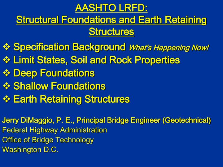
AASHTO LRFD: Structural Foundations and Earth Retaining Structures. Specification Background What’s Happening Now! Limit States, Soil and Rock Properties Deep Foundations Shallow Foundations Earth Retaining Structures Jerry DiMaggio, P. E., Principal Bridge Engineer (Geotechnical)

E N D
AASHTO LRFD:Structural Foundations and Earth Retaining Structures • Specification Background What’s Happening Now! • Limit States, Soil and Rock Properties • Deep Foundations • Shallow Foundations • Earth Retaining Structures Jerry DiMaggio, P. E., Principal Bridge Engineer (Geotechnical) Federal Highway Administration Office of Bridge Technology Washington D.C.
AASHTO Specification Background: Geotechnical Engineering Presence * TRB/ NCHRP Activities (A LOT!) * Geotechnical Engineering does NOT have a broad based presence on AASHTO SubCommittees and Task Forces as do other technical specialties. * SubCommittee on Construction (guide construction specs) * SubCommittee on Materials (specs on materials and testing standards) * SubCommittee on Bridges and Structures (specs on materials/ systems, design, and construction)
History of AASHTO: Design & Construction Specifications for Bridges and Structures * First structural “Guideline Specification” early 1930s (A code yet NOT A code!). * First “significant” Geotechnical content 1989. * First LRFD specification 1994 (Current – 2004, 3rd edition). * First REAL Geotechnical involvement in Bridge SubCommittee activities @ 1996. (Focus on mse walls). * Technical advances to Standard Specifications STOPPED in 1998 to encourage LRFD use (secret). * Major rewrites needed to walls and foundations sections (NOW COMPLETE).
“Geotechnical Scope”: AASHTO Design & Construction Specifications for Bridges and Structures * Topics Included: Subsurface Investigations, soil and rock properties, shallow foundations, driven piles, drilled shafts, rigid and flexible culverts, abutments, WALLS (cantilever, mse, crib, bin, anchor). * Topics NOT addressed: integral abutments, micropiles, augercast piles, soil nails, reinforced slopes, and ALL SOIL and ROCK EARTHWORK FEATURES.
Standard and LRFD AASHTO Specifications * Currently AASHTO has 2 separate specifications: Standard specs 17th edition and LRFD, 2004 3rd edition. * Standard Specifications use a combination of working stress and load factor design platform. * LRFD uses a limit states design platform with different load and resistance factors (than LFD).
LRFD IMPLEMENTATION STATUS Geotechnically, most States still use a working stress approach for earthworks, structural foundations, and earth retaining structures. Several States have totally adopted LRFD. Many State Geo/Structural personnel and consultants ARE NOT FAMILAR with the content of LRFD 3rd edition. “AASHTO and FHWA have agreed that all state DOTs will use LRFD for NEW structure design by 10/07.”
What are UNIQUE Geotechnical issues related to LRFD? * Strong influence of construction on design. * GEOTECHs strong bias toward performance based specifications. * Natural variability of GEO materials. * Variability in the type, and frequency of tests, and method to determine design property values of soil and rock. * Differences between earthwork and structural foundation design model approaches. * Influence of regional and local factors. * General lack of data on limit state conditions.
What Happening Now? * FHWA sponsored a complete rewrite of Section 10 during 2004. The rewrite was prepared by National subject matter experts and had broad input from a number of Key State Dots, (including T-15 member States), and the Geotechnical community (ASCE - GI, DFI, ADSC, PDCA). * During the Proposed spec development @ 2000 comments were addressed. The Proposed spec was then distributed to all States for review. An additional @ 1000 comments were addressed. * The revised Proposed Specification was advanced and approved by the AASHTO’s Bridge and Structures Sub-Committeee in June 2005. The revised Proposed Specification is used in the NHI LRFD Substructure course which currently available.
Fundamentals of LRFD Principles of Limit State Designs * Define the term “Limit State” * Define the term “Resistance” * Identify the applicability of each of the four primary limit states. * Understand the components of the fundamental LRFD equation.
A Limit State is a defined condition beyond which a structural component, ceases to satisfy the provisions for which it is designed. Resistance is a quantifiable value that defines the point beyond which the particular limit state under investigation for a particular component will be exceeded.
Resistance can be defined in terms of: * Load/Force (static/ dynamic, dead/ live) * Stress (normal, shear, torsional) * Number of cycles * Temperature * Strain
Limit States * Strength Limit State * Extreme Event Limit State * Service Limit State * Fatigue Limit State L I S T
Rn / FS QShigiQi≤ Rr = fRn hi = gi = Qi = Rr = f = Rn = Load modifier (eta) Load factor (gamma) Force effect Factored resistance Resistance factor (phi) Nominal resistance
ShigiQi≤ Rr = fRn Qn Rn f(g,) Qn Probability of Occurrence Rn R Q Q or R
Subsurface Materials * Soil * Rock * Water * Organics
10.4 SOIL AND ROCK PROPERTIES 10.4.1 Informational Needs 10.4.2 Subsurface Exploration 10.4.3 Laboratory Tests 10.4.3.1 Soil Tests 10.4.3.2 Rock Tests 10.4.4 In-situ Tests 10.4.5 Geophysical Tests 10.4.6 Selection of Design Properties 10.4.6.1 Soil Strength 10.4.6.1.1 Undrained strength of Cohesive Soils 10.4.6.1.2 Drained Strength of Cohesive Soils 10.4.6.1.3 Drained strength of Granular Soils 10.4.6.2 Soil Deformation 10.4.6.3 Rock Mass Strength 10.4.6.4 Rock Mass Deformation 10.4.6.5 erodibility of rock
Soil Characteristics * Composed of individual grains of rock * Relatively low strength * Coarse grained (+ #200) * High permeability * Fine grained (- #200) * Low permeability * Time dependant effects
Rock Characteristics * Strength * Intermediate geomaterials,qu = 50-1500 psi * Hard rock, qu > 1500 psi * Rock mass properties
Undrained Strength of Cohesive Soils, su Vane Shear Test f=0 su s qu Unconfined Compression su = qu/2 Typical Values su = 250 - 4000 psf
Drained Strength of Cohesive Soils, c’ and f’f Triaxial Compression CU Test Typical Values c’ = 100 - 500 psf f’f = 20o - 35o
Guided Walk Through For N160 = 10, select ’f = 30o
Soil Deformation Initial elastic settlement (all soils) 0 -2 -4 -6 -8 -10 -12 Settlement (in) 1 10 100 1000 10000 Time (days) Primary consolidation Secondary consolidation Fine-grained (cohesive) soils
Consolidation Properties eo p’ = Preconsolidation Stress 1 Cr Void Ratio (e) Cc Cs 0.5 0.1 1 10 100 Log10v’
Stress Range, 40 – 80 kPa 2.65 2.6 2.55 2.5 2.45 2.4 2.35 2.3 2.25 One log cycle De=Ca=0.06 Void ratio (e) tp 0.1 1 10 100 1000 10000 Elapsed Time (min)
Elastic Properties of Soil • Young’s Modulus, Es • Typical values, 20 – 2000 tsf • Poisson’s Ratio, u • Typical values, 0.2 – 0.5 • Shear Modulus, G • Typical values, Es / [2 (1 + u)] • Determination by correlation to N160 or su, or in-situ tests
Rock Properties • Laboratory testing is for small intact rock specimens • Rock mass is too large to be tested in lab or field • Rock mass properties are obtained by correlating intact rock to large-scale rock mass behavior – failures in tunnels and mine slopes • Requires geologic expertise
Intact Rock Strength Unconfined Compression, qu Typical Values qu = 1500 - 50000 psi Point Load Test
Rock Quality 0.8 ft Sound 0.7 ft Not sound, highly weathered Not sound, centerline pieces < 4 inches, highly weathered Length, L 0.8 ft Sound 0.6 ft Core Run Total = 4 ft 0.2 ft Not sound Sound 0.7 ft CR = 95% RQD = 53%
CSIR Rock Mass Rating System • This system is based on qu, RQD, joint spacing, joint condition and water condition.
Rock Mass Strength Shear stress, t f’i t C1’ stm s3 s s1 Effective Normal Stress, s’ f’i = tan-1(4 h cos2[30+0.33sin-1(h-3/2)]-1)-1/2 t = (cot f’i – cos f’i)mqu/8 h = 1 + 16(ms’n+squ)/(3m2qu)
Intact Rock Deformation, Ei • Typical values range from 1000 to 13000 ksi Poisson’s Ratio, u • Typical values range from 0.1 to 0.3
Rock Mass Deformation (psi x 106) 90 70 50 30 10 12 10 8 6 4 2 In situ modulus of deformation, EM (GPa) Ea = 2 RMR - 100 10 30 50 70 90 Rock mass rating RMR
Read More About It GEC 5 FHWA-IF-02-034
Jerry A. DiMaggio P. E.Principal Bridge Engineer TEL: (202) 366-1569FAX: (202) 366-3077 The best Geotechnical web site in town! www.fhwa.dot.gov/bridge WOW! FREE STUFF FROM THE FEDERAL GOVERNMENT!