Download
1 / 65
660 likes | 771 Vues
Physical Layer. Radio Models: modulation, encoding, antenna, “capture” Propagation models: free space; fading Multiplexing (bandwidth sharing): FDMA, TDMA, CDMA. MAC Layer. Media Access Control protocol: coordination and scheduling of transmissions among competing neighbors

E N D
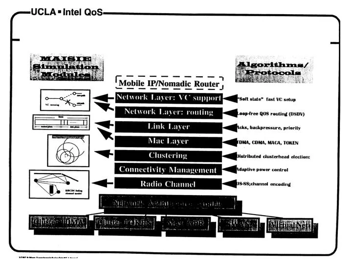
Physical Layer • Radio Models: modulation, encoding, antenna, “capture” • Propagation models: free space; fading • Multiplexing (bandwidth sharing): FDMA, TDMA, CDMA
MAC Layer • Media Access Control protocol: coordination and scheduling of transmissions among competing neighbors • Goals: low latency, good channel utilization; best effort + real time support • MAC layer clustering: aggregation of nodes in a cluster (= cell) for MAC enhancement; different from network layer clustering/partitioning such as used for routing.
Frequency Hopping (FH) • Frequency spectrum sliced into frequency subbands (eg, 125 subbands in a 25 Mhz range) • Time is subdivided into slots; each slot can carry several bits (slow FH) • A typical packet covers several time slots • A transmitter changes frequency slot by slot (frequency hopping) according to unique, predefined sequence; all users are clock and slot synchronized • Ideally, unique sequences are “orthogonal” (ie, non overlapped); in practice, come conflicts may occur
MAC protocols reviewed • CSMA (Packet Radio Net) • MACA, MACA-BI • IEEE 802.11 • PRMA • MACA/PR • Cluster TDMA • Bluetooth • HomeFR
Multiple Access Links and Protocols Three types of links: (a) Point-to-point (single wire) (b) Broadcast (shared wire or medium; eg, E-net, wireless, etc.) (c) Switched (eg, switched E-net, ATM etc) We start with Broadcast links. Main challenge: Multiple Access Protocol
Multiple Access Control (MAC) Protocols • MAC protocol: coordinates transmissions from different stations in order to minimize/avoid collisions • (a) Channel Partitioning MAC protocols • (b) Random Access MAC protocols • (c) “Taking turns” MAC protocols • Goal: efficient, fair, simple, decentralized
Channel Partitioning MAC protocols • TDM (Time Division Multiplexing): channel divided into N time slots, one per user; inefficient with low duty cycle users and at light load. • FDM (Frequency Division Multiplexing): frequency subdivided.
Channel Partitioning (CDMA) • CDMA (Code Division Multiple Access): exploits spread spectrum (DS or FH) encoding scheme • unique “code” assigned to each user; ie, code set partitioning • Used mostly in wireless broadcast channels (cellular, satellite,etc) • All users share the same frequency, but each user has own “chipping” sequence (ie, code) • Chipping sequence like a mask: used to encode the signal • encoded signal = (original signal) X (chipping sequence) • decoding: innerproduct of encoded signal and chipping sequence (note, the innerproduct is the sum of the component-by-component products) • To make CDMA work, chipping sequences must be chosen orthogonal to eachother (ie, innerproduct = 0)
CDMA (cont) CDMA Properties: • protects users from interference and jamming (used in WW II) • protects users from radio multipath fading • allows multiple users to “coexist” and transmit simultaneously with minimal interference (if codes are “orthogonal”) • requires “chip synch” acquisition before demodulation • requires careful transmit power control to avoid “capture” by near stations in near-far situations • FAA requires use of SS (with limits on tx power) in the Unlicensed Spectrum region (ISM), eg, .9 Ghz and 2.4 Ghz (WaveLANs) • CDMA used in Qualcomm cellphones (channel efficiency improved by factor of 4 with respect to TDMA)
Random Access protocols • A node transmits at random (ie, no a priory coordination among nodes) at full channel data rate R. • If two or more nodes “collide”, they retransmit at random times • The random access MAC protocol specifies how to detect collisions and how to recover from them (via delayed retransmissions, for example) • Examples of random access MAC protocols: (a) SLOTTED ALOHA (b) ALOHA (c) CSMA and CSMA/CD
Slotted Aloha • Time is divided into equal size slots (= full packet size) • a newly arriving station transmits a the beginning of the next slot • if collision occurs (assume channel feedback, eg the receiver informs the source of a collision), the source retransmits the packet at each slot with probability P, until successful. • Success (S), Collision (C), Empty (E) slots • S-ALOHA is channel utilization efficient; it is fully decentralized.
Slotted Aloha efficiency If N stations have packets to send, and each transmits in each slot with probability P, the probability of successful transmission S is: S = Prob (only one transmits) = N P (1-P)^(N-1) Optimal value of P: P = 1/N For example, if N=2, S= .5 For N very large one finds S= 1/e (approximately, .37)
Pure (unslotted) ALOHA • Slotted ALOHA requires slot synchronization • A simpler version, pure ALOHA, does not require slots • A node transmits without awaiting for the beginning of a slot • Collision probability increases (packet can collide with other packets which are transmitted within a window twice as large as in S-Aloha) • Throughput is reduced by one half, ie S= 1/2e
CSMA (Carrier Sense Multiple Access) • CSMA: listen before transmit. If channel is sensed busy, defer transmission • Persistent CSMA: retry immediately when channel becomes idle (this may cause instability) • Non persistent CSMA: retry after random interval • Note: collisions may still exist, since two stations may sense the channel idle at the same time ( or better, within a “vulnerable” window = round trip delay) • In case of collision, the entire pkt transmission time is wasted
CSMA/CD (Collision Detection) • CSMA/CD: carrier sensing and deferral like in CSMA. But, collisions are detected within a few bit times. • Transmission is then aborted, reducing the channel wastage considerably. • Typically, persistent retransmission is implemented • Collision detection is easy in wired LANs (eg, E-net): can measure signal strength on the line, or code violations, or compare tx and receive signals • Collision detection cannot be done in wireless LANs (the receiver is shut off while transmitting, to avoid damaging it with excess power) • CSMA/CD can approach channel utilization =1 in LANs (low ratio of propagation over packet transmission time)
Wireless ground radio networks (cont’d) (b) wireless LANs • mostly indoor • base station ( like cellular); or ad hoc networking (mostly point to point) • standards: IEEE802.11; HiperLAN (ETSI)
Wireless LAN Configurations Peer-to-peer Networking Ad-hoc Networking BS With or without control (base) station
IEEE 802.11 Standard (Wireless LANs) • Basic Service Set: single hop ad hoc network • Extended Service Set: multiple BSSs interconnected via wired net • Physical Layer: DSSS, FHSS, IR (1 or 2 MBPS) • MAC: several options: (a) DCF (Distr. Coord. Funct): CSMA or RTS-CTS-DATA; phy and virtual carrier sense; pos ACK; p-persistent; binary backoff; priority access via staggered Inter Frame Spacing (IFS) eg., short IFS > high priority (ACKs, CTS) (b) PCF (Point Coord.Funct): polling performed from Access Point (AP) ; connection oriented mode; PCF and DCF cycles are repeated (PCF repetition interval)
Voice support in IEEE 802.11 (Sobrinho, Krishnakumar Globcom 96) • DCF mode, with CSMA • voice has priority over data (short IFS) • voice users tx staggered "black bursts", proportional to waiting time (and speech bytes in buffer) • voice user who waited longest wins • pos ACK guarantees success (no hidden term.) • voice connections tend to evenly spread out in time frame Possible Improvement: • instead of pos ACK, neg ACK (less OH) • receiver "invites" the sender with neg ACK if did not receive pkt after time out
PRMA (Packet Reservation Multiple Access) • Developed at WINLAB,Rutgers (D. Goodman) • Cellular system for voice and data • Two separate carriers for upstream (terminal to base station) & downstream (base station to terminal) • A derivative of Reservation ALOHA (once you got a slot in the frame, you keep it until you clear your backlog)
PRMA (cont’d) • Upstream channel: slotted time frame, with available and reserved time slots • Successful terminal obtains reservation until it quits transmission • Base station broadcasting feedback packet (success, collision, empty slot) at the end of each frame • ALOHA contention with permission probability p (i.e. contending terminal transmits in available slot with prob. p)
frame k contending terminals: 6,4 R5 R5 R5 R6 A A R2 R2 R2 R11 R11 R11 R1 R1 R1 R8 R8 A A A A R4 R3 A - - transmitting terminals frame k+1 2 11 6,4 1 5 8 contending terminals: 6,4 - - transmitting terminals 2 4 6 11 1 5 frame k+2 contending terminals: 12 - - transmitting terminals 2 4 6 11 12 5 A: available slot Rx: slot reserved for terminal x PRMA protocol example