Download
1 / 32
340 likes | 920 Vues
Tolerances Cylindrical Fits & Geometric Tolerances. A Dimensioning Technique That Ensures the Interchangeability of Parts. Lockheed SR 71. Learning Objectives. Apply linear tolerances in both the English and Metric systems.

E N D
TolerancesCylindrical Fits & Geometric Tolerances A Dimensioning Technique That Ensures the Interchangeability of Parts
Learning Objectives • Apply linear tolerances in both the English and Metric systems. • Calculate the following parameters, given a dimensioned set of mating parts: Allowance, Clearance, Hole Tolerance, Shaft Tolerance. • Match Geometric Tolerance symbols with their meaning. • Apply Geometric tolerances with AutoCAD.
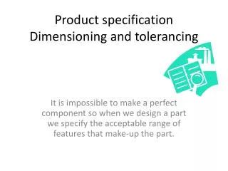
Tolerance ??? • The Oxford English dictionary defines tolerance as: b. In Mech., an allowable amount of variation in the dimensions of a machine or part. More widely, the allowable amount of variation in any specified quantity Or, paraphrased… “Tolerance is how accepting of errors you are”.
General Concepts • A measurement with a zero tolerance is impossible to manufacture in the real world. • Tolerances on parts contribute to the expense of a part, the smaller the tolerance the more expensive the part.
Types of Tolerances • General Tolerances –Limit the error a machinist is allowed on all dimensions, unless otherwise specified • Linear Tolerances –Specific error limits for a particular linear measurement. • Geometric Tolerances– Errorlimits, not on the size, but on the shape of a feature.
General Tolerance • Are specified in the title block of a drawing. • Must always be included on “real” parts. .
Linear Tolerance • Is an overriding tolerance which specifies a tolerance for one specific dimension. • Can be listed in limit or deviation form, but normally should be specified on an engineering drawing in limit form. • Should only be used in the case of real necessity, not just because. • ?? WHY ???
Example of Linear Tolerance • The parts shown to the right illustrates a linear tolerance shown in limit form.
“Forms” of Linear Tolerance • Unilateral. Variation in one direction • Bilateral. Variation in two directions • Limit. Max & Min.. largest on top
Terminology: • There are four parameters of interest: • Hole Tolerance. • Shaft Tolerance. • Allowance. • Maximum Clearance.
Hole Tolerance • The difference between the diameters of the largest and smallest possible holes. • Determines the cost of manufacturing the hole. • Does not consider the Shaft at all.
Shaft Tolerance • The difference between the diameters of the largest and smallest possible shafts. • Determines the cost of the shaft. • Does not consider the Hole at all.
Allowance • The tightest fit between two mating parts. • Determines how the two parts will interact with one another. • Smallest hole minus largest shaft. • Or the “gap” between smallest hole & largest shaft. • Does not affect the cost of the parts.
Maximum Clearance • The loosest fit between mating parts. • Determines how the two parts will interact with one another. • Largest hole minus smallest shaft. • Or the “gap” between largest hole hole & smallest shaft. • Does not affect the cost of the parts.
Formulas for calculation • Hole Tolerance = LH - SH • Shaft Tolerance = LS - SS • Allowance = SH - LS • Maximum Clearance = LH - SS LH=Large Hole, SH=Small Hole LS-Large Shaft, SS=Small Shaft
Other definitions • Nominal Size - The approximate size of a part. • Actual Size - The measured size of a finished part. • Basic Size - The exact theoretical size for a part, used to calculate the acceptable limits. • Hole Basis - A system of fits based on the minimum hole size as the basic diameter.
Practical Application • This class is not trying to teach the design aspect of tolerance • We will be interested in applying a given tolerance to a part, not in determining the “best” tolerance • Various industries (aerospace, electronics, automotive, etc.) set their own tolerances.
Types of Fits • Linear tolerances can be classified in 4 major categories, based on the interaction between the parts : • Clearance Fit. • Line Fit. • Transition Fit. • Interference Fit (Force Fit).
English Example Note that all values are listed in thousandths of an inch. See Essential of Engineering Design Graphic Appendix A, Table 8-12
English Example • Running and sliding fit RC9 • Basic diameter 2.00” • Hole limits +7.0, 0 • Shaft limits -9.0, -13.5 • Max Clear .0205 • Allowance .0090 • Hole Tolerance .0070 • Shaft Tolerance .0045
Clearance Fit • In a clearance fit, the two parts will always fit together with room to spare
Clearance Fit • In a clearance fit, the two parts will always fit together with room to spare • As a team, calculate the: Hole Tolerance. .0007 Shaft Tolerance. .0004 Allowance. .0006 Clearance. .0017
Line Fit • In a line fit, the two parts may fit together with no room to spare
Line Fit • In a line fit, the two parts may fit together with no room to spare • As a team, calculate the: Hole Tolerance. .0007 Shaft Tolerance. .0010 Allowance. 0 Clearance. .0017
Transition Fit • In a transition fit, the two parts may either clear or interfere with each other…probably the cheapest way to manufacture products. Used with selective assembly process
Transition Fit • In a transition fit, the two parts may either clear or interfere with each other • As a team, calculate the: Hole Tolerance. .045 Shaft Tolerance. .051 Allowance. -.037 Clearance. -.059
Interference Fit • In an interference fit, the two parts will always interfere with each other, requiring a force or press fit
Interference Fit • In an interference fit, the two parts will always interfere with each other, requiring a force or press fit • As pairs, calculate the Hole Tolerance. .013 Shaft Tolerance. .016 Allowance. -.037 Clearance. -.008
English Fits • ANSI standards list five type of fits: • RC: Running and Sliding Clearance Fits • LC: Clearance Locational Fits • LT: Transition Locational Fits • LN: Interference Locational Fits • FN: Force and Shrink Fits • Each of these has several classes (Appendix A) • The higher the class number, the greater the tolerance and the looser the fit.
Metric Fits See Appendix A page 199 in Essentials of EDG.. By Vinson Clearance Fits Transition Interference
Metric Example • H11/c11 (loose running) • Basic diameter 40 mm • Hole size 40.160,40.000 • Shaft size 39.880,39.720 • Max Clear 0.440 • Allowance 0.120 • Hole Tolerance 0.160 • Shaft Tolerance 0.160