Download

1 / 66
660 likes | 911 Vues
Key Technologies of PTN - OAM. V1.0. Contents. Basic Concepts of OAM MPLS-TP OAM Ethernet OAM. OAM: The short form of Operation, Administration and Maintenance.

E N D
Contents • Basic Concepts of OAM • MPLS-TP OAM • Ethernet OAM
OAM: The short form of Operation, Administration and Maintenance. Operation: Mainly includes the routine network status analyzing, alarm monitoring and performance controlling, such as fault detection, fault classification, fault locating, and fault notification. Administration: Mainly includes the analyzing, forecasting, planning and configuring of the network and service, such as performance monitoring, performance analyzing and performance controlling. Maintenance: Mainly includes the testing and fault management of the network and services, such as the protection mechanism and the recovery mechanism. Definition of OAM
Contents • Basic Concepts of OAM • MPLS-TP OAM • Ethernet OAM
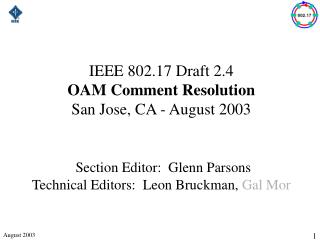
MPLS-TP OAM provides precise end-to-end operation, administration and maintenance Section PE E1 PWE3 PE P ATM PWE3 Tunnel Ethernet PWE3 Section OAM: PHY layer OAM: Guarantee the ring network protection and save the bandwidth. PW OAM: Monitor the connection and performances of the services, create excellent environment for end-to-end management of the service. Tunnel OAM: \Implement the monitoring and protection on the LSP layer. Prvent the performance decline due to the increase of OAM service. • The PTN OAM has a hierarchical architecture which is similar to that of the SDH. • Via layered monitoring, detect and locate the failure quickly. • PTN OAM adopts the carrier-class design of SDH. The OAM function is based on the hardware, which supports the fixed 3.3ms OAM protocol packets monitoring.
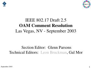
Hierarchical Structure of MPLS-TP OAM • Channel layer - TMC: the channel layer indicates the features of the service, such as the type of connection, the type of topology (point-to-point, point-to-multi points, multi points-to-multi points), and the type of service etc. Its function is similar to the pseudo wire or the virtual circuit layer in PWE3. • Path layer -TMP: The path layer indicates the features of the end-to-end logical connection. Its function is similar to the tunnel layer in IETF MPLS. • Section layer - TMS: The section layer is optional. It indicates the physical connection, such as the SDH (Synchronous digital hierarchy), OTH (Optical Transport Hierarchy), the Ethernet or wavelength channel. PTN PE PE CE CE P Tunnel 1 Tunnel 1 Tunnel 2 Tunnel 2 Section Section Tunnel / Path PW / Channel
Maintenance Entity (ME) The ME is an entity to be managed. It represents the relationship between the two MEPs. The basic ME in MPLS-TP is the MPLS-TP path. Nesting is allowed between MEs, but interleaving between more than two MEs is not allowed. ME Group (MEG) A MEG is a group of MEs which belong to the same management domain and have the same MEG level, and these MEs must belong to the same MPLS-TP connection. MEG End Point (MEP) MEP is used to mark the start and the end of the MEG. It can initiate and terminate the fault management OAM frame and the performance monitoring OAM frame.MEP can be used to test the connectivity of the link. MEG Intermediate Point (MIP) MIP is the intermediate point of the MEG. It can have some impact on the OAM frame, but it cannot initiate the OAM frame. The MIP can select certain actions for some OAM packets, and it can transmit the MPLS-TP frames transparently. MEG Level (MEL) The MEL is used to identify the MEG packets layers in multi-MEG nesting. The OAM frame of each MEG must be identified. MPLS-TP OAM Terms
MPLS-TP OAM Network Model For a MPLS-TP network, the OAM frame of different management domain will be initiated at the MEP of the domain boundary. The node between the source MEP and the destination MEP is MIP. All MEPs and MIPs are configured by the management plane or control plane, where the management plane configuration can be implemented on the NMS or according to the local management manual.
TMC/TMP/TMS Layer Detection OAM can be used in the detection of the following three layers: OAM detection on the TMC layer, used to detect whether the pseudo wire in PWE3 is faulty. OAM detection on the TMP layer, used to detect the whole tunnel. OAM detection on the TMS layer, used to protect the segments of the tunnel. The OAM packets for each layer contains corresponding labels.
OAM frame OAM frame OAM frame MEL plus 1 MEL minus 1 OAM frame MPLS-TP OAM Multi-MEG Enbedding There are 2 MEGs in the network, one is TMC MEG 10, the other one is TMP MEG 20. TMP MEG 20 is embedded in TMC MEG 10. 1) When the OAM frame is generated at the TMC X point, the MEL=0. 2) When the OAM frame enters the TMP MEG 20, the NEL=1. 3) When the OAM frame leaves the TMP MEG 20, the MEL=0. 4) When the OAM frame is received by the TMC Y point, the MEL=0. And the TMC Y point will start to process the frame.
Common OAM Frame Structure • The OAM packet carries the dedicated OAM label, which is used to identify the protocol packet of the OAM detection function so as to distinguish the packet from the other packets. Each MEP or MIP can recognize and process the OAM packets.
Common OAM PDU Format The fields are defined as follows: The 4-byte OAM label is made up of the Label, MEL, S, and TTL fields. This label is contained in all the OAM packets. Label: 20-bit, the value is "14". RFC3032 has define 4 reserved label values, and "14" is recommended for OAM; MEL: 3-bit, it indicates the MEG layer, the value range is 0-7; S: 1-bit, the value is always "1". It indicates the packet to be processed by the OAM module; TTL: 8-bit, it indicates the hop-count. The header of MPLS-TP OAM packet is made up of the Function Type, Res, Version, Flags, and TLV Offset fields. The header is contained in all the OAM packets. Res: the 3-bit reserved field, the value is "000"; The contents of the Version, Flags, TLV Offset fields are depending on the specific OAM packets (e.g. CV, RDI, and FDI);
Common OAM PDU Format Function Type: 8-bit, used to identify the type of OAM packet. The following table lists the OAM function types.
MPLS-TP OAM Functions • Alarm Management Function • CC • AIS • RDI • LB • LT • Lck • TST • Performance Management Function • LM • DM • Other OAM Functions • APS • MCC • CSF • SCC • SSM
MPLS-TP OAM Functions • Alarm-related OAM Functions • CC (Continuity and Connectivity Check): check whether the connection is normal. • AIS (Alarm Indication Signal): used to notify the client layer that the path to the server layer is invalid. • RDI (Remote Defect Indication): used to inform the remote end that the remote end is faulty. • eLB(Loopback):The loopback is initiated by the MEP. The loopback function is implemented by MEP or MIP. • LT (Link Tracing):Used to search the neighboring relationship and locate the problem. • Lck(Lock): used to inform the MEP that the corresponding service layer or sub-layer MEP has aborted the service. According to this signal, the MEP will know whether the interruption is scheduled or caused by failure. • TST(Testing):Used to diagnose the service interruptions.
MPLS-TP OAM Functions Performance-related OAM Functions LM (Frame Loss Measurement): used to measure the amount of frame loss between two MEPs. DM (Packet Delay and Packet Delay Variation Measurements): used to measure the delay and delay variation when the packets are transmitted from one MEP to another MEP or during the whole process that the packets are transmitted between the two MEPs. Other OAM Functions APS (Automatic Protection Switching): It is defined by G.8131/G.8132. It is used to send the APS frame to protect the switching. MCC (Management Communication Channel): used to send the MCC frame to transmit the management data. CSF (Client Signal Fail): used to transmit the signal failure on the client layer from the source of the MPLS-TP path to the sink of the MPLS-TP path. SCC (Signaling Communication Channel): used to provide the control plane channel. SSM (Synchronization Status Message): used to transmit the synchronization message.
Alarm Management The alarm management provides the functions including alarm detection, fault verification, fault locating and fault notification. It is used to work together with the NMS to improve the reliability and availability of the network. It is the most important part of the MPLS-TP OAM. Alarm Management Methods: Continuity check Alarm indicator Remote defect indication Link tracing Loopback Lock Test
Continuity Check (CC) It periodically sends the CV frames containing the CC information between the source MEP and destination MEP to check whether the connection is under normal status. This function can detect the loss of continuity between the MEPs and the mismerge of MEGs. It also can detect error MEP connection and other defects (e.g. error MEP or error period). It is mainly used for fault management, performance monitoring and switching protection. The types of CC message sending period include: 1s for fault management (1 frame/second), 100ms for performance monitoring (10 frames/second), and 3.33ms for switching protection (300 frames/second).
When the MEP receives a CV/CC frame, it will immediately check whether the MEG ID in the frame is consistent with the MEG ID in the MEP and whether the MEP ID is contained in the corresponding MEP ID list. The defects can be detected by comparing this information with the configuration information in the destination MEP. Detection Process (from top to bottom): 1. If the destination MEP doesn't receive the CV/CC frames within 3.5 sending periods (i.e. 10ms), "loss of continuity (LOC)" occurs. 2. If the destination MEP receives the CV/CC frames, but the MEL in the frame is lower than that of the destination MEP, "Unexpected MEL" occurs. 3. If the destination MEP receives the CV/CC frames, the MEL in the frame is the same with that of the destination MEP, only the MEG IDs are different, "Mismerge" occurs. 4. If the destination MEP receives the CV/CC frames, the MEL and MEG ID in the frame are the same with that of the destination MEP, only the MEP IDs are different, "Unexpected MEP" occurs. 5. If the destination MEP receives the CV/CC frames, the MEL, MEG ID and MEP ID in the frame are the same with that of the destination MEP, only the period range is different from the sending period of CC message, "Unexpected Period" occurs. CC alarm restriction relationship: LOC>mismerge>Unexpected MEP>Unexpected Period Fault Management - CC Function
Alarm Indication Signal (AIS) AIS is used to notify the client layer that the connection is faulty after the defect on the service layer is found, and to suppress the LOC alarm from the client layer at the same time. It is very important for preventing the alarm chain and starting the troubleshooting procedure promptly. When the defect occurs on the service layer, the MEP will initiate the FDI/AIS frames according to the MEL of the client layer, and it will periodically send the frames to the MEP of the client layer until the defect is cleared. After all the defects are cleared, the MEP can stop initiating the AIS. If the MEP doesn't receive the FDI/AIS frames within 3.5 periods for receiving the AIS message, the MEP will clear off all the alarms and the AIS defects.
AIS Implementation Process Check the AIS and restrain the LOC alarms from all the corresponding MEPs. If there is no AIS, you can resume the continuity checking. Trigger: defects on the service layer, including that signaling is invalid when CC is valid or AIS connection is locked when CC is invalid FDI/AIS frame
Fault Management - RDI Function The RDI function is used to notify the remote end that the local end is faulty when the alarm on the local end is detected. It is similar to the RDI of SDH. It is accompanied by the AIS alarm. It is only applicable to the bi-directional connection. RDI is contained in the CV packet. It only requires to add a RDI identifier in the "flags" field of the CC frame.
Trigger: MEP defects CV/RDI frame Check the RDI RDI Implementation Process • Fault management of single end: when the RDI defect is associated with the other defects in the MEP, network failure may occur. If the single MEP has not receives the RDI, it means the entrance of the entire MEG is normal. • Performance monitoring of remote end: input the performance monitoring program to show whether the remote end has any error. • Difference between RDI and BDI:RDI is very similar to BDI, and its functions all can be implemented by BDI. The difference is that RDI doesn't support the unidirectional P-to-MP MPLS-TP connection.
Uni-cast LB As an on-demand OAM function, uni-cast loopback can be used to check the bidirectional connectivity between the MEP and the MIP (or the peer MEP), it also can be used to test the bidirectional service interruption between the pair of peer MEPs, such as check the throughput of bandwidth and check the bit error. The uni-cast LB messages include the uni-cast LB request and uni-cast LB response, which are contained in the LBM frame and LBR frame respectively. The uni-cast LB can implement the bi-directional connectivity test and diagnosis test functions. The two functions cannot be implemented at the same time. Before starting to execute the on-demand commands of the new application, you have to terminate all the commands related to the previous application. When starting the LB function, you should configure the local MEP node. The loopback status should be "enabled", the loopback type should be "connection test" or "diagnosis test"; The peer end node should be MEP or MIP node, and the other LB parameters can be the default value.
Check the MEP MAC and the sequence number in the LBR. Received the LBR within 5 seconds? Check the LB Target MIP and the Transaction ID. Bi-directional connection(MEP->MIP) Diagnostic test (MEP->MEP) Uni-cast LB Implementation Process Difference between LB and CC: Both LB and CC can be used to check the connectivity. LB is suitable for testing the bi-directional connectivity failure, CC is suitable for testing the uni-directional connectivity failure. In the actual application, you should use both methods to confirm the failure.
Implementation of Unicast LB Key stage: judging the validity of the LBR frame. The details are as follows: When the function is used to verify the connectivity, the source MEP will judge whether the “LB Target MIP/MEP MAC Address” and “Transaction ID” are correct and determine whether the frame is received within 5 seconds after the LBM frame is sent. If yes, the frame is valid; if not, the frame will be dropped. When the function is used for diagnosis test, the source MEP mainly judges whether the "Target MIP/MEP MAC Address" is the same with its MAC address and whether the "Sequence Number" is valid (according to the testing signal receiver). If yes, the frame is valid; if not, the frame will be dropped. Besides, the MIP can judge the validity of the received LBR frame by comparing whether the "Target MIP/MEP MAC Address" is the same with its MAC address. If not, the LBR frame will be dropped. Note: The two functions cannot be implemented at the same time. Before starting to execute the on-demand commands of the new application, you have to terminate all the commands related to the previous application.
Multi-cast LB Multi-cast LB is used to test the bi-directional connectivity between the MEP and multiple peer MEPs. Multi-cast LB is more complicated than uni-cast LB. In the multicast LB, the MEP needs to send the list of all the peer MEPs with bi-directional connectivity to the source MEP. The multicast LB messages include the multicast LB request and multicast LB response, which are contained in the LBBM frame and LBBR frame respectively.
Link Trace (LT) LT is Used to search the neighboring relationship and locate the problem. It is mainly used in: Neighbor relationship retrieval: The LT function can be used to recognize the neighbor relationship between the MEP and the remote MEP or MIP. Fault locating: The LT function can be used to locate the fault. When the fault (e.g. link or device problem) or forwarding plane loop occurs, the sequence of the MIP and/or MEP may be different from the expectation. The difference in sequence provides information for locating the fault.
Lock (LCK) The LOCK function is used to inform the adjacent client layer MEP of its scheduled management or diagnostic behavior. This function enables the client layer MEP to distinguish the errors from the data stream interruption caused by scheduled management or diagnostic behaviors of the service layer MEP. The MEP needs to report the interruption caused by errors, and it doesn't need to report the interruption caused by scheduled behaviors.
Implementation process of LCK function: when the source end function of the MEP is locked, the MEP will send the LCK packets to the peer end. If the sink functions are locked, the MEP will send the MEP packets to all the MEPs on its client layer. The period of sending the LCK packets is 1 second. The MEP stops forwarding the packets to the locked end during the locking period. Implementation Process of LCK Check the LCK condition. If the MEP doesn’t receive the LCK frame within 3.5 periods, remove the LCK. Trigger: MEP is locked under management/diagnostic behavior MEL LCK frame
Test (TST) The TST function is used to diagnose the uni-directional on-demand service interruption, including checking the throughput of bandwidth, the frame loss and the bit error. These functions are implemented by inserting the TST frames that have specific throughput, frame size, and sending model. And the TST frames contain the testing signal information.
Implementation Process of TST When the TST implements the interruptive service test of MPLS-TP, the customer data traffics are broken in the diagnosed entity. The MEP configured for interruptive service test will send the LCK frames to the adjacent client layer (sub-layer). When the TST implements the non-interruptive service test function of MPLS-TP, the data traffics will not be broken, and the MEP will send the frames that contain the MPLS-TP test signal information. So that the restrained service bandwidth can be fully used. Before implementing this function, you need to confirm the transmission rate of the TST frames in advance.
Performance Management The function of performance management is to improve the quality of network service and the efficiency of network operation. For this purpose, the performance management module should provide the functions including performance monitoring, performance analysis and performance control, as well as database maintenance. It also needs to start the fault management system when it finds serious performance decline. The performance management of the MPLS-TP network is implemented mainly by collecting and measuring the QoS data. The performance parameters mainly include: Fame loss ratio (FLR): FLR refers the percentage of the lost frames among the total amount of sent frames during the interval T in the point-to-point MPLS-TP connection. Frame delay (FD): FD refers to the loopback delay of the frames. The loopback delay means the interval between the time when the first bit of the frame is sent by the source node and the time when the last bit of the frame is received by the same source node. The loopback action is conducted by the destination node of the frame. Frame delay vibration (FDV): FDV is used to measure the vibration of delay for the two frames with the same service level in the MPLS-TP connection.
Frame Loss Measurement (LM) The main function of LM is to provide the frame loss statistics, icluding the frame loss ratio and the amount of lost frames at the near end, the frame loss ratio and the amount of lost frames at the remote end. It is used to calculate the difference of the amounts of the sent and received frames at the outgoing and incoming interfaces in the point-to-point MPLS-TP connection. It is implemented by sending and receiving the LM frame between a pair of MEPs, combined with the maintenance of the two local counters TxFCI and RxFCI. TxFCI counts the frames sent to the peer MEP, RxFCI counts the frames received from the peer MEP. The default sending period is 100ms. Near-end frame loss: It refers to the frame loss at the incoming interface of the MPLS-TP connection. It may cause the near-end severe error seconds (Near-end SES). Far-end frame loss: It refers to the frame loss at the outgoing interface of the MPLS-TP connection, and it may cause the far-end severe error seconds (Far-end SES). LM function includes the dual-end LM and the single-end LM. The LM function is also divided into the pre-activated LM and the on-demand LM. If the CV packet sending function is started, the pre-activated LM will be started automatically by default.
Frame Delay Measurement (DM) The DM function is one of the on-demand OAM functions. It can be used to measure the frame delay and the frame delay vibration. The function is implemented by sending the DM frames between the source MEP and the destination MEP periodically during the diagnostic interval. The detailed operation method is to set the time stamps in the request and response frame and calculate the difference. The DM of MPLS-TP includes the uni-directional DM and the bi-directional DM. The frame carrying the uni-directional DM information is called as the 1DM frame. The frame carrying the bi-directional DM information is called as the DMM frame. The frame carrying the response DM information is called as the DMR frame. In the MPLS-TP network, the uni-directional DM has very strict requirements for the clock synchronization between the sending MEP and the receiving MEP. If the clocks are not synchronized, it can only measure the uni-directional frame delay vibration. In contrast, the bi-directional frame delay measurement can get accurate result easily, and it doesn't require clock synchronization.
Implementation Process of DM • In order to let the result of bi-directional frame delay measurement to be more accurate, the receiving MEP can configure the RxTimeStamp_f and TxTimeStamp_f information in the DMR frames. Then the bi-directional frame dealy can be calculated as follows: • Frame Delay = ( RxTime_b–TxTimeStamp_f ) – ( TxTimeStamp_b–RxTimeStamp_f ) IDM, configure TxTimeStamp_f IDM, configure RxTime_f Request DMM, configure TxTimeStamp_f Reply DMR, configure RxTime_b
Contents • Basic Concepts of OAM • MPLS-TP OAM • Ethernet OAM
MPLS-TP Position of Ethernet OAM Ethernet network Link layer CFM In-domain:CFM Link layer CFM In-domain:CFM
Basic Functions of Ethernet OAM Ethernet OAM is used to manage the links between the two directly connected devices, and it mainly provides the following functions: OAM capability discovering Fault notification Remote loopback Link monitoring
OAM Capability Discovering OAM capability discovering is the foundation of the OAM mechanism. The device that implements the Ethernet OAM must detect the OAM capability of the remote DTE device. The OAM discovering must be conducted before the OAM operation. The Ethernet OAM interaction can be started normally only after the consistent OAM peer end is discoverd. There are two types of OAM: Active OAM: The active OAM can initiate the link discovering and remote loopback functions actively. Passive OAM: The passive OAM cannot initiate the link discovering and remote loopback actively, but the other processing operations are the same with that of the active OAM. In actual configuration, one end must be active OAM. If both ends are passive OAM, the capability discovering cannot be succeeded.
Display after Successful Discovery 9000-3(config)#show ethernet-oam gei_2/20 discovery PortId 20: Ethernet OAM Enable Local DTE ----------- Config: Mode : active Mode of local end Period : 1*100(ms) Packet sending period of local end Link TimeOut : 2(s) Over-long time Unidirection : nonsupport PDU Max Size : 1518(bytes) Status: Parser : forward Under forwarding state Multiplexer : forward Stable : yes Discovery : done Loopback : off PDU Revision : 0 Remote DTE ----------- Config: Mode : active Mode of remote end Link Monitor : support Unidirection : nonsupport Remote Loopback : support Mib Retrieval : nonsupport PDU Max Size : 1518 OUI : zte Status: Parser : forward Under forwarding state Multiplexer : forward Stable : yes Mac Address : 00.d0.d0.c0.0b.80 Remote MACaddress(I f sending failed, the characters in this field will be all “0”. ) PDU Revision : 0
Fault Notification This function periodically sends the OAM PDU via the Ethernet OAM device. The PDU contains the TLV information of the local device and the TLV information of the remote device. The device can get to know the status of the remote link or local link from the data interaction. The notification displayed on the device is the fault alarm. For example, when the port shutdown occurs,the alarm indicator will be displayed.
The remote loopback is configured for certain purpose on the point-to-point peer end device by the network administrator. When the remote device is in loopback status, it will not forward the data packets normally, but it will send all the received non-OAM packets to the source port. This function can be used in fault locating and packet loss testing. All packets except for the OAM packets Initiator of the loopback Data stream Diagram of Remote Loopback Remote Loopback
Link Monitoring The link monitoring function is used to send the event notification to inform the peer end of the detected fault. It has two parameters, the window size and the threshold value. The typical fault notification events include: Error symbol period event: it counts the error symbols in the packet window and determines whether to generate the event notification according to the preset threshold value of the error symbol. Error frame event: it counts the error frames in the specific period and determines whether to generate the event notification according to the preset threshold value of the error frame. Error frame period event: it counts the error frames in the specific packet window and determines whether to generate the event notification according to the preset threshold value of the error frame. Error frame seconds accumulated event: it counts the error frames in the specific period and determines whether to generate the event notification according to the preset threshold value of the error frame seconds.
Ethernet OAM is classified into two levels: Ethernet Link layer OAM, EFM:Ethernet in the First Mile Ethernet service layer OAM, CFM:Connectivity Fault Management Classification of Ethernet OAM
Ethernet Link Layer (EFM) Ethernet Link Layer OAM technology (EFM): Based on the IEEE 802.3ah agreement, EFM is used to solve the problem in the final mile to the customer. It is usually used on the physical Ethernet link between the UPE device and the CE device of the network for monitoring the status of the link between the customer's network and the operator's network so as to guarantee that the networks are reliable and stable. EFM is implemented on the data link layer of the Ethernet, which is an optional sub-layer. The position of the OAM sub-layer in the data link layer flow is shown as follows:
Fucntions of EFM Information OAM PDU The information OAM PDU implements the automatic discovering of the heartbeat signal. After the OAM link is created, the MEP will periodically send the information OAM PDU to monitor the link. The information OAM PDU contains the local and remote TLV information. The link monitoring is implemented via periodical exchanging of OAM PDU packets. If the MEP doesn't receive the information OAM PDU within the specified period, it means the link layer has some problem. Event notification OAM PDU: The event notification OAM is used to inform the remote end of the link status alarms, such as emergent link event, link events (error signal period, error frame, error frame period, error frame accumulated seconds) and the events specified by the customer. When the amount of the errors on the link is lager than the threshold value, the OAM will send responding OAMPDU event notification packets to the peer end. The alarm may be local emergency alarm. The OAM can notify the peer end device via it.
Functions of EFM Variable Request and Variable Response OAM PDU To request and respond to one or multiple MIB variables of the remote DTE. In the variable request OAMPDU, the local device encapsulates the MIB variables of the requested peer end device into the request packet and sends them to the peer end device. When the peer end device receives the variable request, it collects the local MIB variable information which is filled in and replied to in the way of variable response OAMPDU. To query remote MIB variable at local end. Via the variable request and variable response function, the final-mile equipment can monitor and manage the user devices. Loopback Control OAM PDU: The loopback control OAMPDU is enabled by an active OAM entity or to disable the peer loopback function of the remote passive OAM. When the loopback function on the remote device is enabled, all non-OAMPDU packets cannot be forwarded and need to be returned to the local end. Therefore, this loopback function is a service-break-off function Specific organization OAMPDU: Reserved OAM packets for device manufacturers.