Download
1 / 29
290 likes | 402 Vues
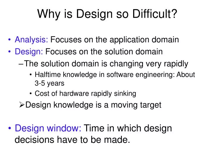
Why is Design so Difficult?. Analysis: Focuses on the application domain Design: Focuses on the solution domain The solution domain is changing very rapidly Halftime knowledge in software engineering: About 3-5 years Cost of hardware rapidly sinking Design knowledge is a moving target

E N D
Why is Design so Difficult? Analysis: Focuses on the application domain Design: Focuses on the solution domain The solution domain is changing very rapidly Halftime knowledge in software engineering: About 3-5 years Cost of hardware rapidly sinking Design knowledge is a moving target Design window: Time in which design decisions have to be made.
Analysis Output: Requirements and System Model Nonfunctional Requirements Object Model Dynamic Model Functional Model
Software Lifecycle Activities class... class... class... class.... Requirements Elicitation Analysis System Design Detailed Design Implemen- tation Testing Implemented By Expressed in Terms Of Structured By Realized By Verified By ? ? Application Domain Objects Solution Domain Objects Use Case Model Source Code Subsystems Test Cases
The Scope of System Design Bridge the gap between a problem and an existing system in a manageable way System Design Problem • How? • Use Divide & Conquer: 1) Identify design goals 2) Model the new system design as a set of subsystems 3-8) Address the major design goals. Existing System
System Design (Architectural Design) • System design is concerned about the overall structure of the system • How is it broken into pieces? How do these pieces fit together? Must they know about each other? • What are the goals it tries to achieve? (Often listed under non functional requirements). Trade-off priorities • Hardware/software allocation: Estimate hardware requirements, Hardware/software trade-offs, Describe processor allocation • Data management: Data structures implemented in memory or secondary storage • Identification of concurrency: Threads of control • Feasibility: Discuss design alternatives, Technological constraints that drive the design, What if the constraints change?
Example of Design Goals Reliability Modifiability Maintainability Understandability Adaptability Reusability Efficiency Portability Traceability of requirements Fault tolerance Backward-compatibility Cost-effectiveness Robustness High-performance • Good documentation • Well-defined interfaces • User-friendliness • Reuse of components • Rapid development • Minimum number of errors • Readability • Ease of learning • Ease of remembering • Ease of use • Increased productivity • Low-cost • Flexibility
Stakeholders have different Design Goals Functionality User-friendliness Usability Ease of learning Fault tolerant Robustness Low cost Increased productivity Backward compatibility Traceability of requirements Rapid development Flexibility Client (Customer) End User Minimum # of errors Modifiability, Readability Reusability, Adaptability Well-defined interfaces Developer/ Maintainer Runtime Efficiency Reliability Portability Good documentation
Typical Design Trade-offs Functionality v. Usability Cost v. Robustness Efficiency v. Portability Rapid development v. Functionality Cost v. Reusability Backward Compatibility v. Readability
Subsystem Decomposition Subsystem Collection of classes, associations, operations, events and constraints that are closely interrelated with each other The objects and classes from the object model are the “seeds” for the subsystems In UML subsystems are modeled as packages Service A set of named operations that share a common purpose The origin (“seed”) for services are the use cases from the functional model Services are defined during system design.
Subsystem Interfaces vs API Subsystem interface: Set of fully typed UML operations Specifies the interaction and information flow from and to subsystem boundaries, but not inside the subsystem Refinement of service, should be well-defined and small Subsystem interfaces are defined during object design Application programmer’s interface (API) The API is the specification of the subsystem interface in a specific programming language APIs are defined during implementation The terms subsystem interface and API are often confused with each other The term API shouldnot be used during system design and object design, but only during implementation.
Subsystem Interface Object Good design: The subsystem interface object describes all the services of the subsystem interface Subsystem Interface Object The set of public operations provided by a subsystem
Coupling and Coherence of Subsystems Goal: Reduce system complexity while allowing change Coherence measures dependency among classes High coherence: The classes in the subsystem perform similar tasks and are related to each other via associations Low coherence: Lots of miscellaneous and auxiliary classes, no associations Coupling measures dependency among subsystems High coupling: Changes to one subsystem will have high impact on the other subsystem Low coupling: A change in one subsystem does not affect any other subsystem Good Design
Example of a Bad Subsystem Decomposition Advertisement User Interface Session Management User Management Tournament Statistics Component Management Tournament
How to achieve high Coherence High coherence can be achieved if most of the interaction is within subsystems, rather than across subsystem boundaries Questions to ask: Does one subsystem always call another one for a specific service? Yes: Consider moving them together into the same subystem. Which of the subsystems call each other for services? Can this be avoided by restructuring the subsystems or changing the subsystem interface? Can the subsystems even be hierarchically ordered (in layers)?
Architectural Style vs Architecture Subsystem decomposition: Identification of subsystems, services, and their association to each other (hierarchical, peer-to-peer, etc) Architectural Style: A pattern for a subsystem decomposition Software Architecture: Instance of an architectural style.
Examples of Architectural Styles Client/Server Peer-To-Peer Repository Model/View/Controller Three-tier, Four-tier Architecture Service-Oriented Architecture (SOA) Pipes and Filters
Properties of Subsystems: Layers and Partitions A layer is a subsystem that provides a service to another subsystem with the following restrictions: A layer only depends on services from lower layers A layer has no knowledge of higher layers A layer can be divided horizontally into several independent subsystems called partitions Partitions provide services to other partitions on the same layer Partitions are also called “weakly coupled” subsystems.
Virtual Machine A virtual machine is a subsystem connected to higher and lower level virtual machines by "provides services for" associations A virtual machine is an abstraction that provides a set of attributes and operations The terms layer and virtual machine can be used interchangeably Also sometimes called “level of abstraction”.
Building Systems as a Set of Virtual Machines A system is a hierarchy of virtual machines, each using language primitives offered by the lower machines. Virtual Machine 4 . Virtual Machine 3 Virtual Machine 2 Virtual Machine 1 Operating System, Libraries Existing System
Closed Architecture (Opaque Layering) Each virtual machine can only call operations from the layer below C1ass1 C1ass2 C1ass3 attr attr attr op op op C1assE C1assF attr attr op op C1assC C1assD attr attr op op C1ass B Class A attr attr op op VM4 VM3 Design goals: Maintainability, flexibility. VM2 VM1
Open Architecture (Transparent Layering) Each virtual machine can call operations from any layer below C1 C1 C1 C1 C1 C1 C1 C1 C1 attr attr attr attr attr attr attr attr attr op op op op op op op op op VM1 VM2 Design goal:Runtime efficiency VM3 VM4
Layered systems are hierarchical. This is a desirable design, because hierarchy reduces complexity low coupling Closed architectures are more portable Open architectures are more efficient Properties of Layered Systems
Example Architectural Style ISO’s OSI Reference Model ISO = International Standard Organization OSI = Open System Interconnection Reference model which defines 7 layers and communication protocols between the layers Application Presentation Level of abstraction Session Transport Network DataLink Physical
Client/Server Architectural Style One or many servers provide services to instances of subsystems, called clients Each client calls on the server, which performs some service and returns the result The clients know the interface of the server The server does not need to know the interface of the client End users interact only with the client Server * * Client +service1() requester provider +service2() +serviceN()
Client/Server Architectures Often used in the design of database systems Front-end: User application (client) Back end: Database access and manipulation (server) Functions performed by client: Input from the user (Customized user interface) Front-end processing of input data Functions performed by the database server: Centralized data management Data integrity and database consistency Database security
Design Goals for Client/Server Architectures Location- Transparency Server runs on many operating systems and many networking environments Service Portability Server might itself be distributed, but provides a single "logical" service to the user Client optimized for interactive display-intensive tasks; Server optimized for CPU-intensive operations High Performance Scalability Server can handle large # of clients User interface of client supports a variety of end devices (PDA, Handy, laptop, wearable computer) Flexibility Server should be able to survive client and communication problems. Reliability
Repository Architectural Style Subsystems access and modify data from a single data structure called the repository Historically called blackboard architecture (Erman, Hayes-Roth and Reddy 1980) Repository Subsystem createData() setData() getData() searchData() * • Subsystems are loosely coupled (interact only through the repository) • Control flow is dictated by the repository through triggers or by the subsystems through locks and synchronization primitives
Repository Architecture Example: Incremental Development Environment (IDE) SemanticAnalyzer Compiler SyntacticAnalyzer Optimizer Parse Tree Symbol Table Repository LexicalAnalyzer CodeGenerator SymbolTable ParseTree SymbolicDebugger SyntacticEditor
Providing Consistent Views Problem: In systems with high coupling changes to the user interface (boundary objects) often force changes to the entity objects (data) The user interface cannot be reimplemented without changing the representation of the entity objects The entity objects cannot be reorganized without changing the user interface Solution: Decoupling! The model-view-controller architectural style decouples data access (entity objects) and data presentation (boundary objects) The Data Presentation subsystem is called the View The Data Access subsystem is called the Model The Controller subsystem mediates between View (data presentation) and Model (data access) Often called MVC.