Download
1 / 104
1.07k likes | 1.41k Vues
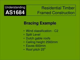
SECTION 8 - RACKING (BRACING) AND SHEAR FORCES WEEK 13. 8.1 GENERAL. Permanent bracing shall be provided to enable the roof, wall and floor framework to resist horizontal forces applied to the building (racking forces).

E N D
SECTION 8 -RACKING (BRACING)AND SHEAR FORCESWEEK 13 AS 1684 SECTION 8 - RACKING AND SHEAR FORCES
8.1 GENERAL Permanent bracing shall be provided to enable the roof, wall and floor framework to resist horizontal forces applied to the building (racking forces). Appropriate connection shall also be provided to transfer these forces through the framework and subfloor structure to the building’s foundation. AS 1684 SECTION 8 - RACKING AND SHEAR FORCES
8.1 GENERAL Where required, bracing within the building,which normally occurs in vertical planes,shall be constructed into walls or subfloor supports and distributed evenly throughout. Where buildings are more than one storey in height, wall bracing shall be designed for each storey. AS 1684 SECTION 8 - RACKING AND SHEAR FORCES
FIGURE 8.1 VARIOUS BRACING SYSTEMS CONNECTING HORIZONTAL DIAPHRAGMS AS 1684 SECTION 8 - RACKING AND SHEAR FORCES
NOTES to Figure 8.1 1. The wind force on unclad frames may be equal to or greater than those on a completed clad or veneered house. AS 1684 SECTION 8 - RACKING AND SHEAR FORCES
NOTES to Figure 8.1 2.Horizontal wind (racking) forces are applied to external surfaces that are supported by horizontal or near horizontal diaphragms. Diaphragms include roofs, ceilings and floor surfaces including their associated framing. AS 1684 SECTION 8 - RACKING AND SHEAR FORCES
NOTES to Figure 8.1 3.Each horizontal diaphragm transfers racking forces to lower level diaphragms by connections and bracing. This continues down to the subfloor supports or concrete slab on the ground, where the forces are then resisted by the foundations. AS 1684 SECTION 8 - RACKING AND SHEAR FORCES
Wind produces horizontal loads on buildings that must be transmitted through the structure to the foundation. AS 1684 SECTION 8 - RACKING AND SHEAR FORCES
In a conventionally constructed house these loads are transmitted to the ground by a complex interaction between the walls, ceiling/roof structure and floor structure. AS 1684 SECTION 8 - RACKING AND SHEAR FORCES
The ceiling and floor form large horizontal diaphragms and normally play an important part in this action as most walls rely on support from this ceiling or floor diaphragm to prevent them blowing over. AS 1684 SECTION 8 - RACKING AND SHEAR FORCES
The wind forces are transmitted to the ceiling diaphragm from the walls and also the roof. They are then transferred through the ceiling diaphragm to the bracing walls that transmit them to the floor structure, foundations and then into the ground. With ceiling diaphragm Without ceiling diaphragm AS 1684 SECTION 8 - RACKING AND SHEAR FORCES
8.2 TEMPORARY BRACING Temporary bracing shall be equivalent to at least 60% of permanent bracing required.Temporary bracing may form part of the installed permanent bracing. AS 1684 SECTION 8 - RACKING AND SHEAR FORCES
8.3.1 General Bracing shall be designed and provided for each storey of the house and for the subfloor, where required, in accordance with the following procedure: AS 1684 SECTION 8 - RACKING AND SHEAR FORCES
Determine the wind classification • Determine the wind pressure • Determine area of elevation • Calculate racking force AS 1684 SECTION 8 - RACKING AND SHEAR FORCES
NOTE: To calculate the number of braces required for wall bracing, the required racking force (kN) is divided by the capacity of each brace. AS 1684 SECTION 8 - RACKING AND SHEAR FORCES
The total capacity of each brace is equal to the length of the brace multiplied by its unit capacity (kN/m) as given in Table 8.18 (pg 141). AS 1684 SECTION 8 - RACKING AND SHEAR FORCES
For example: a diagonal brace Type (c) (as per Table 8.18) has a total capacity of 1.5 kN/m Multiplied x length of bracing wall = 1.5kN/m x 2.4m = 3.6 kN for a 2.4 m long section of braced wall. AS 1684 SECTION 8 - RACKING AND SHEAR FORCES
8.3.1 General (f) Check even distribution and spacing (g) Check connection of bracing to roof/ceilings and floors AS 1684 SECTION 8 - RACKING AND SHEAR FORCES
8.3.2 Wind pressure on the building Wind pressures on the surfaces of the building depend on the wind classification, width of building and roof pitch. Tables 8.1 to 8.5 give pressures depending on these variables. AS 1684 SECTION 8 - RACKING AND SHEAR FORCES
When wind flows over a building it applies different pressures (forces) on a flat vertical wall to that on the sloping roof surface. Pressure on roof - 0.77 kPa* Pressure on wall - 1.10 kPa* * These values are indicative only and will vary with roof pitch, building height to depth ratio etc. The tables need to know the ratio between how much roof area the wind ‘sees’ as opposed to how much wall area the wind ‘sees’. The building width and roof pitch will establish this ratio. AS 1684 SECTION 8 - RACKING AND SHEAR FORCES
8.3.2 Wind pressure on the building Pressures are given for single storey and upper storey of two storeys for both long wind at 90O to the ridgeand short wind parallel to the ridge sides of the building, and lower storey of two storeys or subfloor for both long wind at 90O to the ridgeand short wind parallel to the ridge sides of the building. AS 1684 SECTION 8 - RACKING AND SHEAR FORCES
8.3.3 Area of elevation The wind direction used shall be that resulting in the greatest load for the length and width of the building, respectively. As wind can blow from any direction, the elevation used shall be that for the worst direction. For example ........... AS 1684 SECTION 8 - RACKING AND SHEAR FORCES
8.3.3 Area of elevation In the case of a single-storey house having a gable at one end and a hip at the other, the gable end facing the wind will result in a greater amount of load at right angles to the width of the house than the hip end facing the wind. Sloping roof surface All vertical surface \ this is the worst wind direction + vertical wall AS 1684 SECTION 8 - RACKING AND SHEAR FORCES
For example, the relatively simple building shape shown in Figure 8.2(A) must be broken into two parts (shapes) in Wind Direction 2 because gable ends are calculated using a different table. After calculating the separate bracing requirements for each part the bracing elements used must also be distributed accordingly. AS 1684 SECTION 8 - RACKING AND SHEAR FORCES
As indicated by Figures 8.2 (A) and Note 1, the area of an elevation includes only the top half of the wall. Note: 1 - h = half the height of the wall (half of the floor to ceiling height). This is the area used to calculate single or upper storey bracing Ceiling diaphragm Floor Slab AS 1684 SECTION 8 - RACKING AND SHEAR FORCES
Ceiling diaphragm Floor diaphragm As indicated by Figures 8.2 (B) and Note 1, the area of an elevation For lower storey of two storey section h = half the height of the lower storey (i.e. lower storey floor to lower storey ceiling) This is the area used to calculate lower storey bracing AS 1684 SECTION 8 - RACKING AND SHEAR FORCES
Note 3 of Figures 8.2 (A, B & C) pg 113 states The area of elevation of the triangular portion of eaves overhang up to 1000 mm wide may be ignored in the determination of area of elevation. Area of Elevation AS 1684 SECTION 8 - RACKING AND SHEAR FORCES
Width Width Width Include the area of enclosed verandah in the total area. Also include any roof area over an open verandah Calculate area of enclosed verandah separately using its width and pitch and distribute bracing accordingly. Do not include areas of open verandahs Open Verandah Open Verandah Enclosed Verandah Enclosed Verandah Building with open and enclosed verandahs, with main roof pitched separately from verandahs. Building with open and enclosed verandahs, with main roof pitched from verandah beams. AS 1684 SECTION 8 - RACKING AND SHEAR FORCES
8.3.4 Racking force(pg 116) The total racking force, in kN, shall be calculated as follows: Projected area of elevation (m2) Lateral wind pressure (kPa) Total racking force x = AS 1684 SECTION 8 - RACKING AND SHEAR FORCES
TABLE 8.1 (pg 116) • Gable ends and flat, vertical surfaces only AS 1684 SECTION 8 - RACKING AND SHEAR FORCES
Table 8.2 is used for determining the pressure on single or upper storey elevations where the wind direction is at 90O to the ridge and for wind speeds N1, N2, N3 & N4. AS 1684 SECTION 8 - RACKING AND SHEAR FORCES
continued WIND 90O TO RIDGE A3 N2 AS 1684 SECTION 8 - RACKING AND SHEAR FORCES
Table 8.3 is used for determining the pressure on lower storey elevations where the wind direction is at90O to a ridge and for wind speeds N1, N2, N3 & N4. AS 1684 SECTION 8 - RACKING AND SHEAR FORCES
continued TABLE 8.3PRESSURE (kPa) ON PROJECTED AREA—LOWER STOREY OR SUBFLOOR OF SINGLE OR TWO STOREY—LONG LENGTH OF BUILDING—HIP OR GABLE ENDS WIND 90O TO RIDGE A3 N2 AS 1684 SECTION 8 - RACKING AND SHEAR FORCES
Table 8.4 is used for determining the pressure on single or upper storey elevations where the wind direction is parallel to a ridge and for wind speeds N1, N2, N3 & N4. AS 1684 SECTION 8 - RACKING AND SHEAR FORCES
WIND PARALLEL TO RIDGE A3 N2 AS 1684 SECTION 8 - RACKING AND SHEAR FORCES
Table 8.5 is used for determining the pressure on lower storey elevations where the wind direction is parallel to a ridge and for wind speeds N1, N2, N3 & N4. AS 1684 SECTION 8 - RACKING AND SHEAR FORCES
WIND PARALLEL TO RIDGE A3 N2 AS 1684 SECTION 8 - RACKING AND SHEAR FORCES
Nominal wall bracing is wall framing lined with sheet materials such as plywood, plasterboard, fibre cement or hardboard, or the like, with the wall frames nominally fixed to the floor and the roof or ceiling frame. (table 9.4 pg 167) 8.3.6.2 Nominal wall bracing (pg 140) AS 1684 SECTION 8 - RACKING AND SHEAR FORCES
The most common nominal bracing material used in houses is plasterboard wall linings. Plasterboard, fixed to the wall frame appropriately (to manufacturers specification) is given ‘structural bracing’ status with a reasonable strength rating. Fixed to the wall frame with nominal fixings, however, its bracing strength is much lower. AS 1684 SECTION 8 - RACKING AND SHEAR FORCES
The maximum amount that can be resisted by nominal wall bracing is 50% of the total racking forces determined from Clause 8.3.4 . Nominal wall bracing shall be evenly distributed throughout the building. If this is not the case, the contribution of nominal bracing shall be ignored. The minimum length of nominal bracing walls shall be 450 mm. 8.3.6.2 Nominal wall bracing AS 1684 SECTION 8 - RACKING AND SHEAR FORCES
The minimum length of nominal bracing walls shall be 450 mm. The bracing capacity of nominal bracing is scheduled in Table 8.17. 8.3.6.2 Nominal wall bracing AS 1684 SECTION 8 - RACKING AND SHEAR FORCES
Where sheet wall lining is placed over the top of a structural brace, the value of the sheet wall lining can not be given its nominal value for the section that overlaps the structural brace. AS 1684 SECTION 8 - RACKING AND SHEAR FORCES
See TABLE 8.18 pg 141 For sheet-braced walls, the sheeting shall be continuous from the top plate to the bottom plate Unless otherwise specified, sheet-bracing walls shall be a minimum of 900 mm wide to satisfy the requirements of their nominated ratings. 8.3.6.3 Structural wall bracing AS 1684 SECTION 8 - RACKING AND SHEAR FORCES
A2 A4 AS 1684 SECTION 8 - RACKING AND SHEAR FORCES
TABLE 8.18 (continued) A3 A4 AS 1684 SECTION 8 - RACKING AND SHEAR FORCES
TABLE 8.18 (continued) A3 A4 AS 1684 SECTION 8 - RACKING AND SHEAR FORCES