Download
1 / 37
370 likes | 561 Vues
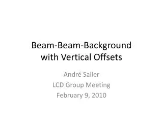
Beam-gas background. Coulomb>> bremsstrahlung. Coulomb BG is naively proportional to P x I. Also depends on beta function over the ring and IR physical aperture. P = 10 -7 Pa is assumed. H. Nakano K. Kanazawa. P = 10 -7 Pa is assumed. Beam-gas Coulomb lifetime. ,. Scattering angle.

E N D
Beam-gas background Coulomb>> bremsstrahlung Coulomb BG is naively proportional to P x I. Also depends on beta function over the ring and IR physical aperture. P = 10-7Pa is assumed
H. Nakano K. Kanazawa P = 10-7Pa is assumed Beam-gas Coulomb lifetime , Scattering angle , y2 s s=s2 s=s1 The minimum scattering angle to hit QC1 beam pipe Beam lifetime is proportional to Rate ∝P x I x <b> x bQC1 / rQC12 Beam-gas lifetime is only x1/100 of KEKB, due to larger vertical beta in QC1 and narrower QC1 physical aperture 2 H.Nakayama (KEK)
Beam Lifetime from Coulomb scattering against residual gas • Parameters (LER) • Gas: CO • Pressure: 1 x 10⁻⁷ Pa • Acceptance • Vertical: QC1: 13.5mm (bym ~ 2888m) • Horizontal: 20 sx • Lifetime • Lifetime calculated(@QC1ap=13.5mm) • 2100 sec (Coulomb) • 1850 sec (Coulomb+ Møller) Z(Z+1) if you include Møllerscattering 14% worse
P = 10-7Pa is assumed LER: by (QC1)= 2900m, <by>=50m, g=7830, rQC1=13.5mm 2100sec cnG = (3x108)x (2.43*1020)x10-7 = 7.29e21; 4pre2S(Z2) /g2/2 = 4p (2.82x10⁻¹⁵)2 x S(62+82)/(7828)2/2 = 7.991e-35; (include Moller: 100=36+64114=42+72, 14% worse) theta_c = 0.036e-3 (by_max = 2900, <by>= 50, QC1=13.5) HER: by(QC1)= 4390m, <by>=54m, g=13700, rQC1=13.5mm 4000sec Belle-II/SuperB Joint BG meeting (Feb. 9-10, 2012)
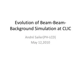
Strategy to reduce Coulomb BG t∝ r2 • Larger QC1 physical aperture (r=10.5mm13.5mm) • Vertical collimators! • QC1 aperture should not be narrowest over the ring • Collimator aperture should be narrower than QC1 aperture • Beam instability? (collimators should be very close(few mm) to the beam ) mm mm LER HER z-axis z-axis Physical aperture e- Physical aperture e+ beta(55.5s) beta(43.5s) beta(85s) [m] [m] [m] beta(66s) We widened QC1 aperture without major change in QCS design. Coulomb lifetime improved (LER: 13602240sec, HER: 21003260sec)
Nakayama Element-by-element simulation Vertical collimator V1 q y2 s=s2 s=s1 QC1 qc: critical angle Taking into causality, hit rate on QC1 from element s1 can be calculated by Sum up for all element s1 over the ring to obtain total hit rate on QC1. Multi-turn loss is also simulated in similar way (Df+=Nturn*Dfturn), also taking in account the causality
Where we should put vertical collimator? Collimator position d[mm] TMC: TMC instability should be avoided. Assuming following two formulae: Aperture Collimator aperture should be narrower than QC1 aperture. > 1.44 mA/bunch(LER) taken from “Handbook of accelerator physics and engineering, p.121” Kick factor (in case of rectangular collimator window) beta[m] We should put collimator where beta_y is SMALL! Belle-II/SuperB Joint BG meeting (Feb. 9-10, 2012)
Candidate collimator locations TMC condition r=13.5mm Collimator width d[mm] (r=10.5mm) TMC condition r=13.5mm (r=10.5mm) LER HER beta_y[m] lerfqlc_1604 herfqlc5605 beta_y[m] • V1 collimator @ LLB3R (downstream) • (s=-90-82m, by=30146m) • by=125m, 2.23mm<d<2.81mm • V1 collimator @ LTLB2 (downstream) • (s=-63-61m, by=81187m) • by=123m, 1.74mm<d<2.26mm Ny(V1)= 1.25, Ny(QC1)= 0.25 Ny(V1)= 42.82, Ny(QC1)= 44.32 Collimator position should satisfy beta_y condition above, need space(at least 1.5m), and the phase should be close to IP
Vertical collimator width vs. Coulomb loss rate, Coulomb life time Based on element-by-element simulation considering causality the phase difference (by Nakayama) Up to 100turns IR loss rate is VERY sensitive to the vertical collimator width. (Once V1 aperture>QC1 aperture, all beam loss goes from V1 to IR Typical orbit deviation at V1 : +-0.12mm (by iBump V-angle: +-0.5mrad@IP )
Beta_y and vacuum level • Vacuum level at large beta_y determines Coulomb lifetime LER Beta_y[m] V1 QC1 ny(1 turn)=44.57 Very important to achieve good vacuum level in these regions Belle-II/SuperB Joint BG meeting (Feb. 9-10, 2012)
Turn-by-turn loss ler1604, V1=LLB3R downstream, d_V1=2.6mm No loss at nturn>40
Confirmation of TMC conditions with realistic model K. Ohmi (KEKB)
Impedance of realistic collimator Dedicated collimator design for small impedance • Round-shape of collimator head • d=5mm(H), d=2mm(V) Y. Suetsugu (KEKB)
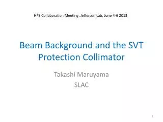
Ith calculated by tracking simulation LER HER sz = 6mm sz = 5mm TMC instability caused by the LER/HER vertical collimators are tolerable.
TMC instability stable sz = 5mm Ith[mA] *beta[m] Calculated by impedance HER 56 sz = 6mm Calculated by formulae sz = 6mm LER 57d24 Rect. head HER 57 unstable d[mm] 17 H.Nakayama (KEK)
Beam-gas summary • Coulomb >> bremsstrahlung • Larger <by> and narrower IR aperture make Coulomb BG much severer at SuperKEKB than at KEKB • Vertical collimators , placed at small beta_y, can reduce beam-gas BG down to ~0.1GHz for LER/HER. • Beam instability for such collimators is confirmed to be tolerable, performing tracking simulation with realistic collimator shape • Vacuum level at large beta_y affects beam-gas lifetime. • Simulation using “SAD” is in preparation • R&D ongoing for collimator which can resist ~100GHz loss Belle-II/SuperB Joint BG meeting (Feb. 9-10, 2012)
backup Belle-II/SuperB Joint BG meeting (Feb. 9-10, 2012)
Suetsugu-san’s slides Belle-II/SuperB Joint BG meeting (Feb. 9-10, 2012)
Bellows Chamber Mask Chamber Bellows Chamber Beam Mask Head (Ti) Design of key components_11 • Movable mask (collimator) • Indispensable in order to reduce background noise of BELL-II • Long R&D history in KEKB • Stealth type was proposed, but not yet realized. • For SKEKB, • High thermal strength against wall heating (~ 1 mm from beam for vertical type) • Low beam impedance (ex. Against TMC instability) • Fitting to antechamber scheme • Robust against impact of beam in case • Placed at both sides of the ring • HOM absorbers (near to masks) • Concept of Ver.4 in KEKB will • be available, at least in the • beginning stage: • how to fit to antechamber • scheme? Ver.4 in KEKB One candidate: PEP-II type KEKB Review 2011 @KEK
Design of key components_12 • Movable masks for KEKB (Ver.4) and PEP-II PEP-II type Pair-type (Two mask heads) “NO structural problem in this design. Intense excited HOM have heated up bellows chambers and NEG elements near the masks.” (from M. Sullivan[SLAC]) KEKB Review 2011 @KEK
Design of key components_13 • Concept of horizontal movable mask RF shield fingers around body (GridCop?) Pair-type d = 5~10 mm 1500 Mask head: Graphite? (t~1 mm?) Length ~0.5 R.L. Mask body: Copper Cooling water Reduced aperture at the mask head eliminates trapped modes. Beam Mask head Cooling water Tapered pipe φ90 KEKB Review 2011 @KEK
Design of key components_14 • Concept of vertical movable mask Pair-type RF shield fingers around body (GridCop?) 1500 Beam φ90 Tapered pipe Mask head d = ~1 mm Cooling water KEKB Review 2011 @KEK
Design of key components_15 • Loss factors (k) • Calculated by GdfidL, 3D model • Dependence on bunch lengths (sz ) • Smaller than that for present Ver.4 (KEKB): owing to long ramp? • Small dependence on d • No big difference between single- and pair-type versions: Pair- type is smaller? d: distance between beam and mask head Log scale (d=10 mm) Single-type (d=5, 10 mm) Single-type Pair-type (d=3, 5 mm) (Thank to K. Shibata) KEKB Review 2011 @KEK
Design of key components_16 • Kick factors (ky) • Calculated by GdfidL, 3D model, sz = 6 mm • Dependence on d Pair-type • Large dependence on d • ky for pair-type is approximately twice of that for single-type. Log scale (V) Horizontal d = 5 mm ky = 81013V/C/m (H) Vertical d = 1 mm ky = 1 1015V/C/m (Thank to K. Shibata and D. Zhou) Ref.:I. Zagorodnovet al., EUROTeV-Report-2006-074 KEKB Review 2011 @KEK
Design of key components_17 • Threshold current for TMC (LER) • Transverse mode coupling instability (TMC) • Threshold formula (from B. Zotter, Handbook of Accelerators) [A/bunch] C1 ~ 8 fs = 2.13 103 Hz E/e = 4 109eV b ~ 20 m (in Arc), ~1 m (in Local Correction) k⊥(sz)= (kick factor, V/C/m) S = (total number) where • Design bunch current = 1.44 mA/bunch • For 1 mask (2 heads) d = 5 mm [H, Arc]: ky= 81013 V/C/m Ith= 43 mA/bunch d = 1 mm [V, Arc]: ky= 1 1015 V/C/m Ith= 3.4 mA/bunch d = 1 mm [V, LC]: ky= 1 1015 V/C/m Ith= 68 mA/bunch (With non-linear collimation scheme) 4 horizontal at arc masks will be available. 1 vertical masks at LC will be OK. KEKB Review 2011 @KEK
Design of key components_18 • Wall loss • For a beam pipe with a radius of a [m], a bunch with a length of z [m], the wall loss per meteris (from A. Piwinski, Handbook of Accelerators) Ib=Bunch current C=Circumference(=3000m) Z0=Vacuum impedance(= 377W) sc=Conductivity (1/W) m = 1, G(3/4) = 1.225 • For d = 1 mm: • If graphite (c=2105 1/Wm) is used, P’=2.55 W/m. For 2500 bunches、P’= 32 kW/m. If ½ of total current concentrated in 1 mm width, P = 50 W/mm2(32 p/2). • Very hard to deal • Iftungsten (c=2107 1/Wm) instead, P = 5 W/mm2 • Well manageable with water cooling. • How about damage? Easy replaceable? KEKB Review 2011 @KEK
設計・製作_19 • 可動マスク(コリメータ) • PEPIIタイプで検討中 • 水平マスク(垂直マスクはヘッドがビームに近く厳しい) • マスクヘッド部の開口を水平・垂直とも狭くすると捕捉モードがない • ロスファクター:~1x10¹¹ V/C @sz=6mm, d = 5 mm:Ver.4 (KEKB)よりも小さい: 長いスロープ(テーパ)のおかげ? Shield fingers • ヘッド長さ:約2 R.L. は欲しい(中村氏) • リング外側にも必要 • 位置決め精度:0.05mm • ビーム位置のフィードバック:両側のBPMを使う? • ビームの衝突に対する対処 1500 Mask head Beam Cooling water Tapered pipe SuperKEKB検討会@KEK
設計・製作_20 • 可動マスク(コリメータ) • TMC(Transverse Mode Coupling Instability) • キックファクター:~2x10¹⁴ V/C@sz=6mm, d = 5 mm • dに大きく依存:d = 1mmで3x10¹⁵ V/C • もしb = 10 m: d= 5mmでは12台でもOK • d = 1mmでは1台程度が限界 • 本当のβで評価する必要あり [A/bunch] • 壁損失 • d =1mmの時、もしグラファイト(c=2105 1/Wm)を用いるとP = 50 W/mm2と非常に厳しい。 • 例えば導電率の良いタングステン(c=2107 1/Wm)では、P= 5 W/mm2と全く問題ない [W/m] (A. Piwinski) SuperKEKB検討会@KEK
設計・製作_21 • 可動マスク(コリメータ) • ヘッド材料:候補 • 基本的に高融点 (ビームロスによる発熱具合に依る。) • 高熱伝導率:冷却 • 高導電率:インピーダンス、ジュール損 • 加工性、接合性、入手の容易さ • 真空特性:低蒸気圧 • ビーム衝突時の温度計算 • EGS4による計算(佐波氏) • 円柱形状の材料にビームを打ち込んで温度上昇を調べた。 • モンテカルロ計算は初期値を振ったペンシルビームで行い、その結果を重ね合わせて、各々のビームサイズの場合の温度上昇を求める。 • ビームサイズρはシ グマで入力し、ラウンドビーム。 円柱はr-zのメッシュに切られている。:実効的にρ ~50 μm SuperKEKB検討会@KEK
設計・製作_22 • 可動マスク(コリメータ) • ヘッド材料:候補) • 計算結果:Moの例 • 計算:1x10¹² e-/pulse:全バンチの入力だとすると、16 mAに相当。 • ビーム電流3.6 Aでは、2.25x10¹⁴ e-/pulse。225倍。融点を実効的に下げたものを赤破線で示す。 • ビームサイズρを約50μmとすると、どの厚さでも溶ける。 • RL=0.5の範囲で、r =2mm = 3000μmなら大丈夫か。 DT MO • r =50μm ⇒ Z [rl] SuperKEKB検討会@KEK
設計・製作_23 • 可動マスク(コリメータ) • ヘッド材料:候補(温度) • 融点との差が小さいもの:Be、C 、Cr、Mo、Ti、W • だが、周回しているビームが全て当たるとどの材質でも溶ける! →容易に(?)ヘッド交換できるようにする。 →できるだけ速いアボートシステムを!! • 1x10¹² e-/pulse(計算条件)、r = 50 mm相当として、各材質で、RL0.5までの最大温度と融点をプロット 最大温度 T 融点 SuperKEKB検討会@KEK
設計・製作_24 • 可動マスク(コリメータ) • ヘッド材料:候補(加工性、接合性) • Mo、W、Taは、ブロックであれば入手に問題なし。接合性はWが良い。 • レアメタル(Ir、Rh)は入手に難(少量なら問題なし?) • Beは加工時注意が必要:2RL必要だと700 ㎜必要! • W、Mo、Ir、Rhの導電率、熱伝導率が良い 最有力⇒ SuperKEKB検討会@KEK
設計・製作_25 • 可動マスク(コリメータ) • 構造案:ヘッド部分を取り換え可能にする? • 両側をユニバーサルベローズ構造にしてオフセット可能とする。 • 場所、数は未確定。Verticalマスクも必要? • 本年度は、タングステンと銅ブロックとの接合(HIP)試験。 • 実機製作は2年後? 詳細検討はこれから 交換可能 SuperKEKB検討会@KEK
可動マスクについて • 可動マスク(コリメータ) • TMC • キックファクター:~1x10¹⁴ V/C@sz=6mm, d = 5 mm • dに大きく依存:d = 1mmで1x10¹⁵ V/C • b = 10 m: d= 5mmでは12台でも大丈夫。 • b = 10 m: d = 1mmでは2台程度が限界 • 正規のβで評価する必要あり。 [A/bunch] C1 ~ 8 fs = 2.13 103 Hz E/e = 4 109eV b [ m] k⊥ (sz) = (kick factor, V/C/m) S = (total number) Ithresh=3.6/2500 =1.44 mA/bunch =4.71016 もし:b ~ 680 m k ~ 71013 V/C/m d~7 mm SuperKEKB検討会@KEK
可動マスクについて • 可動マスク(コリメータ) • TMC Z0 = 377 W c = 3.0108 m/s sz = 6 mm q = slope angle ~0.063 h = 50 mm SuperKEKB検討会@KEK