Download
1 / 11
110 likes | 252 Vues
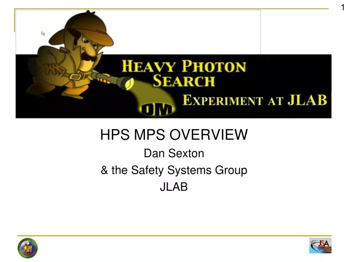
HPS MPS OVERVIEW Dan Sexton & the Safety Systems Group JLAB. HPS MPS OVERVIEW. The MPS System for the HPS Experiment will make use of the same infrastructure and hardware that is utilized in CEBAF and the other experimental halls. HPS MPS Elements Beam Loss Monitors Analog Monitoring

E N D
HPS MPS OVERVIEW Dan Sexton & the Safety Systems Group JLAB
HPS MPS OVERVIEW The MPS System for the HPS Experiment will make use of the same infrastructure and hardware that is utilized in CEBAF and the other experimental halls. D. Sexton, Overview of the MPS for the HPS experiment HPS MPS Elements Beam Loss Monitors Analog Monitoring Limit Switches Halo Counters New Vacuum Valves MPS Electronics BLM Card Analog Card Electrical Card Hall Master New FSD Master
Beam Loss Monitors • Provide early detection of beam loss in critical areas to prevent the loss from becoming a catastrophic event. • The BLMs are mounted near the beam line in areas where loss is expected or of critical concern. • The HVPS channel for each BLM acts as the gain control which is calibrated during initial setup. • Current from the BLM is proportional to the loss detected. • Once the current goes above the set threshold the 5MHz FSD output will be removed causing beam termination. • EPICS status of these channels are available for diagnostic and other uses. • Locations • Previously located will be moved over to the VME controls from the present CAMAC system. • New BLMs are planned for the additional Girders and HPS apparatus HV Power Supply ………. BLM 5 MHz = OK BLM BLM MPS HALL MASTER . . . BLM • The new VME card is tested, commissioned, and installed in CEBAF as part of the 12 GeV effort. This will allow us the opportunity to replace the legacy CAMAC controls since we need to install additional channels anyway. The existing cabling will be used and this will reduce an additional CAMAC crate from the system. D. Sexton, Overview of the MPS for the HPS experiment
Analog Monitoring • Provide analog monitoring circuitry for windows of acceptable ranges. 0-5V, +/- 5V, 0-10V, or +/- 10V Input Ranges • Monitors Analog input channels and provides FSD permit within in the acceptable window. • Uses and Locations • Magnet Power Supply Current – This monitors the box supply currents and ensures that the energy of the magnets is properly set. • Temperature – Connected to the analog output of temperature monitoring components for over temperature protection • Spares available 5 MHz = OK MAGNET P.S. MPS HALL MASTER TEMP. UNIT MAGNET P.S. • Currently there are two of these cards installed in the Hall that will be either relocated to the new MPS rack closer to the HPS experiment or cabled to this location. The cables will be routed from the relocated power supplies to the determined location of this MPS Card. D. Sexton, Overview of the MPS for the HPS experiment
MPS Electrical Card Designed to interface with external signal of 5MHz, 24VDC, or 5VDC. • Summation of 12 available channels for FSD OK • Maskable channels for unused or tune up beam • Channel faults when external signal isn’t present • Input selection type can be changed via on board selection • Uses and Locations • PLC handshake between Hall B Controls and MPS • DC Power Supply interface. • Additional Channels for spares and “oh it would be nice if….” 5 MHz = OK MAGNET P.S. MPS HALL MASTER LIMIT SWITCHES HALL B PLC ETC….. • This is a new VME based design that will be operationally commissioned during the hot checkout of the MPS. All hardware checks and operations have been completed and software group is developing drivers presently. D. Sexton, Overview of the MPS for the HPS experiment
Hall B Beam Line MPS Nothing will change in terms of existing MPS (all vacuum valves are the same, tagger magnet, beam lost monitors …). The additional components will be added as needed. • NEW COMPONENTS • Vacuum Valves • Others? D. Sexton, Overview of the MPS for the HPS experiment
HPS Beam line in the Hall • Two new girders with MPS requirements • HPS Apparatus with MPS requirements BPM, 2-QA, and H-V-correctors HPS Shield wall 2H01 nA BPM YAG viewer H-V-correctors and BPMs Vacuum valves D. Sexton, Overview of the MPS for the HPS experiment Slide Courtesy of StepanStepanyan
New girders – MPS Additions Halo Counter Girder-II ETA2H03 LIMIT SWITCHES Possible BLM Girder-I • Beam Loss Monitors will be added in these specific locations: • Exit of Girder 2 after collimater • Two additional BLMs will be located at the front side of the Girder for Diagnostics and Spare. • Provisions for Limit Switches to protect from beam exposure D. Sexton, Overview of the MPS for the HPS experiment D. Sexton, Overview of the MPS for the HPS experiment
HPS chicane design status HALL B HALO COUNTERS 5 MHz = OK FIBER FSD NODE • Halo Counters located on 1st Girder and on HPS Chicane. • EPICS Adjustable Count Limits • Excessive counts will cause an FSD fault Halo Counters D. Sexton, Overview of the MPS for the HPS experiment
FSD Master Interface • HPS has requested status of the FSD signal for specific startup sequence • This will be a 5MHz signal coming back from the Injector which will be converted to a set of contacts that can be interfaced to the HPS Controls PLC FSD MASTER 5 MHz= OK HALL MASTER HALL B MPS NODES 5MHz to CONTACT CLOSURE NC NO In Hall B the 5MHz return from the Injector will be a summation of all of the MPS needed for Hall B operations: Injector, NL, SL, BSY, and HB. ELECTRICAL BLM ETC. ANALOG HALL B CONTROLS D. Sexton, Overview of the MPS for the HPS experiment
HPS MPS Summary and Goals • Hall specific elements that require MPS interface are being solved with standard MPS Hardware • Additional Channels will be made available and can be added in as needed • Provides an opportunity to upgrade the Hall B MPS hardware with latest revisions. • First steps towards segmented MPS System • Status Feedback from FSD for Hall B controls knowledge of beam availability Questions??? D. Sexton, Overview of the MPS for the HPS experiment