Download
1 / 25
250 likes | 366 Vues
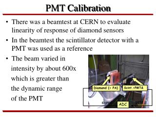
Commercial helicon sources need heavy magnets and cannot cover large substrates. The PMT (Trikon) MØRI source. Solution 1: Use distributed sources. Experiment at PMT, ca 1995. However, still need a large electromagnet. Solution 2: Use permanent magnets. Material: NdFeB Bmax = 12 kG.

E N D
Commercial helicon sources need heavy magnets and cannot cover large substrates The PMT (Trikon) MØRI source
Solution 1: Use distributed sources Experiment at PMT, ca 1995 However, still need a large electromagnet
Solution 2: Use permanent magnets Material: NdFeB Bmax = 12 kG The magnets are dangerous! The innovation involves two parts: 1. Novel use of PMs 2. Use of the low-field peak effect. UCLA
Internal field External field The field of annular permanent magnets Plasma created inside the rings follows the field lines and cannot be ejected. The field reverses at a stagnation point very close to the magnet.
External field Internal field Proof of principle on 3” diam tube The bottom curve is when the tube is INSIDE the magnet
Mechanism of the Low Field Peak Constructive interference of reflected wave Basic helicon relations UCLA
Low-field peak Design of discharge tube: maximize the loading resistance Calculations are done using the HELIC code of D. Arnush
Medusa 2: An 8-tube linear test array Top view UCLA
Probe ports The array source is vertically compact Side view The magnets can be made in two pieces so that they hold each other on an aluminum sheet. Once placed, the magnets cannot easily be moved, so for testing we use a wooden support. UCLA
Antenna connections For CW operation, all connections were solidly soldered, and RG/393 teflon-insulated cable was used. Cable connectors cannot take the startup voltage. UCLA
Matching circuit for N tubes in parallel The problem with array sources is that the cable lengths cannot be short. The match circuit cannot be close to all the tubes. UCLA
Matching sets limits on antenna inductance and cable lengths. There is a “sweet spot” for tube design when RF is considered. C1, C2 for N=8, L = 0.8mH, Z1 = 110 cm, Z2 = 90 cm
A water-cooled, 50-W, low resistance, rectangular transmission line
0 3.5 Density profiles across the chamber Compact configuration, 3kW Side Langmuir probe << 4” below tubes << 7” below tubes UCLA
-7 0 7 14 Density profiles across the chamber Staggered configuration, 3kW Bottom probe array UCLA
Density profiles along the chamber Staggered configuration, 3kW Bottom probe array UCLA
Density profiles along the chamber Compact configuration, 3kW Bottom probe array UCLA
A compact, stackable module The match circuit fits on top of the array