Download
1 / 27
270 likes | 282 Vues
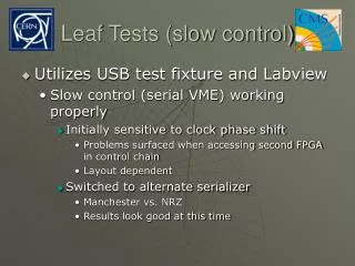
Slow Control. PC. 12:30 12.3 12:45 17.2 13:20 15.2 14:10 17.3 15:20 16.2 18:30 21.3 19:20 18.2 19:45 19.2. Slow Control. HV. Temperature, pressure, …. Valves. 12345. Terminal Server. PLC. RS232. GPIB. ???. 15 ° C. Ethernet. heater. MIDAS DAQ.

E N D
PC 12:30 12.3 12:45 17.2 13:20 15.2 14:10 17.3 15:20 16.2 18:30 21.3 19:20 18.2 19:45 19.2 Slow Control HV Temperature, pressure, … Valves 12345 Terminal Server PLC RS232 GPIB ??? 15° C Ethernet heater MIDAS DAQ
Slow Control Bus HV Temperature, pressure, … Valves heater MIDAS DAQ
ADuC812 / C8051Fxxx Micro controllers with 8x12 bit ADC, 2x12 bit DAC, digital IO RS485 bus over flat ribbon cable Powered through bus Costs ~30$ Piggy back board Generic node www.cygnal.com
Generic node with signal conditioning Sub-master with power supply and PC connection (Parallel Port, USB planned) Integration on sensors, in crates RS232 node with protocol translator Crate Oriented • 19” crate with custom backplane • Generic node as piggy-back • Cards for analog IO / digital IO / °C / 220V • crate connects to parallel port (USB) 2 Versions BUS Oriented
Midas Slow Control Bus • 256 nodes, 65536 nodes with one level of repeaters • Bus length ~500m opto-isolated • Boards for voltage, current, thermo couples, TTL IO, 220V output • Readout speed: 0.3s for 1000 channels • C library, command-line utility, Midas driver, LabView driver • Nodes are “self-documenting” • Configuration parameters in EEPROM on node • Node CPU can operate autonomously for interlock and regulation (PID) tasks (C programmable) • Nodes can be reprogrammed over network http://midas.psi.ch/mscb
HV System Design Vin 2400V • • • 12 times • • • ADC Vout 0-2400V DAC • Cheap and stable (<0.3V) HV system • Regulate global external voltage • Use series of opto-couplers • Compensate non-linearities of opto-couplers by regulation loop • ADC and DAC from slow control node
High Voltage System External HV mC node Opto-couplers
Regulates common HV source 0-2400V, ~1mA DAC 16bit, ADC 14bit Current trip ~10ms Self-calibration with two high accuracy reference voltages Accuracy <0.3V absolute Boards with 12 channels, crates with 192 channels 30$/channel (+ext. HV) HV performance Prototype
DAQ Hardware and Software
m e DAQ Requirements n PMT sum 0.511 MeV meg 51.5 MeV menng 50 51 52 E[MeV] t ~100ns (menn)2 + g • g’s hitting different parts of LXe can be separated if > 2 PMTs apart (15 cm) • Timely separated g’s need waveform digitizing > 300 MHz • If waveform digitizing gives timing <100ps, no TDCs are needed g e m
pb Domino Sampling Chip • Existing: • 0.5 – 1.2 GHz sampling speed • 128 sampling cells • Readout at 5 MHz, 12 bit • ~ 60 $/channel • Needed: • 2.5 GHz sampling speed • Circular domino wave • 1024 sampling cells • 40 MHz readout • < 100ps accuracy C. Brönnimann et al., NIM A420 (1999) 264
input Domino Ring Sampler (DRS) • Free running domino wave, stopped with trigger • Sampling speed 2 GHz (500ps/bin), trigger gate sampling gives 50ps timing resolution • 1024 bins 150ns waveform + 350ns delay
DRS Prototype 4mm • 0.25mm Process (“CERN is using”) • 768 cells • Wafer back July ‘02 1mm . . . . .
Domino Simulation “Analog Extracted” • 16 cells • All paracitics included • Domino speed: 1.5-2.2 GHz
DAQ Board • 9 channels 1024 bins / 40 MHz = 230 ms acceptable dead time • Zero suppression in FPGA • QT Algorithm in FPGA (store waveform if multi-hit) domino wave 8 channel DRS 3.3V 2.5V VME Interface (Cypress) 3 state switches 8 channel DRS FPGA FADC 40 MHz 12 bit 8 channel DRS 8 inputs FADC SRAM 8 channel DRS FPGA FADC FPGA SRAM trigger gate Trigger Input SRAM Board inter-connect SRAM shift register Trigger BUS (2nd level tr.) SRAM
DAQ Topology Trigger Board PMT trigger gate • LXe • e+ counter DSC FADC FPGA CPU 40MHz 2GHz Waveform or QT readout • wires • strips DAQ board trigger gate Trigger Board CPU 100MHz DC 2nd level trigger Waveform or QT readout 2nd level trigger
Pile-up rejection • From (g-2): • 400 MHz sampling • Rise time ~5ns • 3.5ns dead time • 5ns separation scope 1GHz sampling 100MHz sampling
Sample Averaging • Rise time ~10ns • Pile-up rejection ~10ns • Shower fluctuations get averaged by sample averaging + =
Cross-Talk • Not so critical for calorimeter • For DC: careful design of on-chamber preamps • Flash ADC (100MHz) AD9218 has internal cross talk of –75 dB (2 x 10⁻⁴) • ADC resolution • DC: 10bit + bin averaging 13.5 bit (10-4 ) • PMT (DRS): 12bit + bin averaging 15.5 bit (2x10⁻⁵ ), dominated by external noise • Manual charge injection at DC preamp to measure cross talk • Residual cross talk can be corrected off-line
Schedule on electronics • Slow control system: ready by Sept. 02 • HV system: • Prototype system debugged by Oct. 02 • Mass production by end of year • DRS • First prototype back in ~weeks • Prototype tested by Nov. 02 • Second prototype designed by Jan. 03 • Second prototype produced by May 03 • Production run in fall 03 • Board production winter 03/04
DAQ System • Use of MIDAS system • Standard DAQ system at PSI and TRIUMF • Used at the large prototype • Event building added recently • Integration into ROOT: Planned until spring 2003 • Distributed DAQ with Linux cluster Logger Frontend ODB Frontend Frontend Analyzer
MIDAS Analyzer • Modular system • Modules can be developed independently • Version control via CVS • MC data can be “injected” between modules • Analyzer attached to Online Database • Same analyzer can be used online and offline Full physics analysis online!
Electronics setup (ideas) Outside (Trigger): Where present Sindrum II electronics is located, but with air conditioning. Similar to 8p experiment @ TRIUMF On platform (DAQ, HV): like in pibeta
Running the experiment • Highly automatized experiment reduces human mistakes, increases stability of experiment and reduces required manpower • For the pb data taking, 1-2 people at PSI and remote control from U.S. was enough • Expected data rate: 2MB/s @ 100Hz • Local tape library and PSI archive reduces tape changing requirements • Offline analysis: Merlin Linux cluster at PSI archive • Operational costs (without “upgrades”): LN2, Gas, tapes, small repairs: estimated 15k$/year
Safety issues • p*V below critical level • Oxygen detector required • No CE certification for Japanese magnet & power supplies (only inspection) • “No principal problem” • LXe storage tanks under investigation