Download

1 / 220
2.22k likes | 2.64k Vues
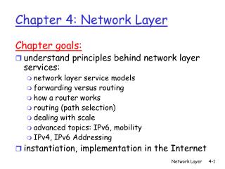
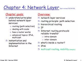
Chapter 4: Network Layer. Chapter goals: understand principles behind network layer services: network layer service models forwarding versus routing how a router works routing (path selection) dealing with scale advanced topics: IPv6, mobility instantiation, implementation in the Internet.

E N D
Chapter 4: Network Layer Chapter goals: • understand principles behind network layer services: • network layer service models • forwarding versus routing • how a router works • routing (path selection) • dealing with scale • advanced topics: IPv6, mobility • instantiation, implementation in the Internet Network Layer
4. 1 Introduction 4.2 Virtual circuit and datagram networks 4.3 What’s inside a router 4.4 IP: Internet Protocol Datagram format IPv4 addressing ICMP IPv6 4.5 Routing algorithms Link state Distance Vector Hierarchical routing 4.6 Routing in the Internet RIP OSPF BGP 4.7 Broadcast and multicast routing Chapter 4: Network Layer Network Layer
transport segment from sending to receiving host on sending side encapsulates segments into datagrams on rcving side, delivers segments to transport layer network layer protocols in every host, router router examines header fields in all IP datagrams passing through it network data link physical network data link physical network data link physical network data link physical network data link physical network data link physical network data link physical network data link physical network data link physical network data link physical network data link physical application transport network data link physical application transport network data link physical Network layer Network Layer
Network Layer 4-4
Two Key Network-Layer Functions • forwarding: move packets from router’s input to appropriate router output • routing: determine route taken by packets from source to dest. • routing algorithms analogy: • routing: process of planning trip from source to dest • forwarding: process of getting through single interchange Network Layer
routing algorithm local forwarding table header value output link 0100 0101 0111 1001 3 2 2 1 value in arriving packet’s header 1 0111 2 3 Interplay between routing and forwarding Network Layer
Connection setup • 3rd important function in some network architectures: • ATM, frame relay, X.25 • before datagrams flow, two end hosts and intervening routers establish virtual connection • routers get involved • network vs transport layer connection service: • network: between two hosts (may also involve intervening routers in case of VCs) • transport: between two processes Network Layer
Example services for individual datagrams: guaranteed delivery guaranteed delivery with less than 40 msec delay Example services for a flow of datagrams: in-order datagram delivery guaranteed minimum bandwidth to flow restrictions on changes in inter-packet spacing Network service model Q: What service model for “channel” transporting datagrams from sender to receiver? Network Layer
Network layer service models: Guarantees ? Network Architecture Internet ATM ATM ATM ATM Service Model best effort CBR VBR ABR UBR Congestion feedback no (inferred via loss) no congestion no congestion yes no Bandwidth none constant rate guaranteed rate guaranteed minimum none Loss no yes yes no no Order no yes yes yes yes Timing no yes yes no no Network Layer
4. 1 Introduction 4.2 Virtual circuit and datagram networks 4.3 What’s inside a router 4.4 IP: Internet Protocol Datagram format IPv4 addressing ICMP IPv6 4.5 Routing algorithms Link state Distance Vector Hierarchical routing 4.6 Routing in the Internet RIP OSPF BGP 4.7 Broadcast and multicast routing Chapter 4: Network Layer Network Layer
Network layer connection and connection-less service • datagram network provides network-layer connectionless service • VC network provides network-layer connection service • analogous to the transport-layer services, but: • service: host-to-host • no choice: network provides one or the other • implementation: in network core Network Layer
call setup, teardown for each call before data can flow each packet carries VC identifier (not destination host address) every router on source-dest path maintains “state” for each passing connection link, router resources (bandwidth, buffers) may be allocated to VC (dedicated resources = predictable service) “source-to-dest path behaves much like telephone circuit” performance-wise network actions along source-to-dest path Virtual circuits Network Layer
VC implementation a VC consists of: • path from source to destination • VC numbers, one number for each link along path • entries in forwarding tables in routers along path • packet belonging to VC carries VC number (rather than dest address) • VC number can be changed on each link. • New VC number comes from forwarding table Network Layer
VC number 22 32 12 3 1 2 interface number Incoming interface Incoming VC # Outgoing interface Outgoing VC # 1 12 3 22 2 63 1 18 3 7 2 17 1 97 3 87 … … … … Forwarding table Forwarding table in northwest router: Routers maintain connection state information! Network Layer
used to setup, maintain teardown VC used in ATM, frame-relay, X.25 not used in today’s Internet application transport network data link physical application transport network data link physical Virtual circuits: signaling protocols 6. Receive data 5. Data flow begins 4. Call connected 3. Accept call 1. Initiate call 2. incoming call Network Layer
no call setup at network layer routers: no state about end-to-end connections no network-level concept of “connection” packets forwarded using destination host address packets between same source-dest pair may take different paths application transport network data link physical application transport network data link physical Datagram networks 1. Send data 2. Receive data Network Layer
Forwarding table 4 billion possible entries Destination Address RangeLink Interface 11001000 00010111 00010000 00000000 through 0 11001000 00010111 00010111 11111111 11001000 00010111 00011000 00000000 through 1 11001000 00010111 00011000 11111111 11001000 00010111 00011001 00000000 through 2 11001000 00010111 00011111 11111111 otherwise 3 Network Layer
Longest prefix matching Prefix MatchLink Interface 11001000 00010111 00010 0 11001000 00010111 00011000 1 11001000 00010111 00011 2 otherwise 3 Examples Which interface? DA: 11001000 00010111 00010110 10100001 Which interface? DA: 11001000 00010111 00011000 10101010 Network Layer
Internet (datagram) data exchange among computers “elastic” service, no strict timing req. “smart” end systems (computers) can adapt, perform control, error recovery simple inside network, complexity at “edge” many link types different characteristics uniform service difficult ATM (VC) evolved from telephony human conversation: strict timing, reliability requirements need for guaranteed service “dumb” end systems telephones complexity inside network Datagram or VC network: why? Network Layer
4. 1 Introduction 4.2 Virtual circuit and datagram networks 4.3 What’s inside a router 4.4 IP: Internet Protocol Datagram format IPv4 addressing ICMP IPv6 4.5 Routing algorithms Link state Distance Vector Hierarchical routing 4.6 Routing in the Internet RIP OSPF BGP 4.7 Broadcast and multicast routing Chapter 4: Network Layer Network Layer
Router Architecture Overview Two key router functions: • run routing algorithms/protocol (RIP, OSPF, BGP) • forwarding datagrams from incoming to outgoing link Network Layer
Input Port Functions Decentralized switching: • given datagram dest., lookup output port using forwarding table in input port memory • goal: complete input port processing at ‘line speed’ • queuing: if datagrams arrive faster than forwarding rate into switch fabric Physical layer: bit-level reception Data link layer: e.g., Ethernet see chapter 5 Network Layer
Three types of switching fabrics Network Layer
Memory Input Port Output Port System Bus Switching Via Memory First generation routers: • traditional computers with switching under direct control of CPU • packet copied to system’s memory • speed limited by memory bandwidth (2 bus crossings per datagram) Network Layer
Switching Via a Bus • datagram from input port memory to output port memory via a shared bus • bus contention: switching speed limited by bus bandwidth • 32 Gbps bus, Cisco 5600: sufficient speed for access and enterprise routers Network Layer
Switching Via An Interconnection Network • overcome bus bandwidth limitations • Banyan networks, other interconnection nets initially developed to connect processors in multiprocessor • advanced design: fragmenting datagram into fixed length cells, switch cells through the fabric. • Cisco 12000: switches 60 Gbps through the interconnection network Network Layer
Output Ports • Buffering required when datagrams arrive from fabric faster than the transmission rate • Scheduling discipline chooses among queued datagrams for transmission Network Layer
Output port queueing • buffering when arrival rate via switch exceeds output line speed • queueing (delay) and loss due to output port buffer overflow! Network Layer
. RTT C N How much buffering? • RFC 3439 rule of thumb: average buffering equal to “typical” RTT (say 250 msec) times link capacity C • e.g., C = 10 Gps link: 2.5 Gbit buffer • Recent recommendation: with N flows, buffering equal to • Scheduling: QoS • AQM, RED Network Layer
Input Port Queuing • Fabric slower than input ports combined -> queueing may occur at input queues • Head-of-the-Line (HOL) blocking: queued datagram at front of queue prevents others in queue from moving forward • queueing delay and loss due to input buffer overflow! Network Layer
Scheduling Policies • scheduling: choose next packet to send on link • FIFO (first in first out) scheduling: send in order of arrival to queue • real-world example? • discard policy: if packet arrives to full queue: who to discard? • Tail drop: drop arriving packet • priority: drop/remove on priority basis • random: drop/remove randomly Network Layer 4-31
Scheduling Policies: more Priority scheduling: transmit highest priority queued packet • multiple classes, with different priorities • class may depend on marking or other header info, e.g. IP source/dest, port numbers, etc.. • Real world example? Network Layer 4-32
Scheduling Policies: still more round robin scheduling: • multiple classes • cyclically scan class queues, serving one from each class (if available) • real world example?
Scheduling Policies: still more Weighted Fair Queuing: • generalized Round Robin • each class gets weighted amount of service in each cycle • real-world example? Network Layer 4-34
4. 1 Introduction 4.2 Virtual circuit and datagram networks 4.3 What’s inside a router 4.4 IP: Internet Protocol Datagram format IPv4 addressing ICMP IPv6 4.5 Routing algorithms Link state Distance Vector Hierarchical routing 4.6 Routing in the Internet RIP OSPF BGP 4.7 Broadcast and multicast routing Chapter 4: Network Layer Network Layer
Host, router network layer functions: ICMP protocol • error reporting • router “signaling” IP protocol • addressing conventions • datagram format • packet handling conventions Routing protocols • path selection • RIP, OSPF, BGP forwarding table The Internet Network layer Transport layer: TCP, UDP Network layer Link layer physical layer Network Layer
4. 1 Introduction 4.2 Virtual circuit and datagram networks 4.3 What’s inside a router 4.4 IP: Internet Protocol Datagram format IPv4 addressing ICMP IPv6 4.5 Routing algorithms Link state Distance Vector Hierarchical routing 4.6 Routing in the Internet RIP OSPF BGP 4.7 Broadcast and multicast routing Chapter 4: Network Layer Network Layer
IP protocol version number 32 bits total datagram length (bytes) header length (bytes) type of service head. len ver length for fragmentation/ reassembly fragment offset “type” of data flgs 16-bit identifier max number remaining hops (decremented at each router) upper layer time to live header checksum 32 bit source IP address 32 bit destination IP address upper layer protocol to deliver payload to E.g. timestamp, record route taken, specify list of routers to visit. Options (if any) data (variable length, typically a TCP or UDP segment) IP datagram format how much overhead with TCP? • 20 bytes of TCP • 20 bytes of IP • = 40 bytes + app layer overhead Network Layer
Don’t Fragment IP datagram format The IPv4 (Internet Protocol) header. • 20 bytes ≤Header Length< (24 – 1) x 4 bytes = 60 bytes • 20 bytes ≤ Total Length < 216 – 1 bytes = 65535 bytes Network Layer 4-39
IP datagram format Some of the IP options. 5-54 Network Layer 4-40
network links have MTU (max. transmission size) - largest possible link-level frame. different link types, different MTUs large IP datagram divided (“fragmented”) within net one datagram becomes several datagrams “reassembled” only at final destination IP header bits used to identify, order related fragments IP Fragmentation & Reassembly fragmentation: in: one large datagram out: 3 smaller datagrams reassembly Network Layer
IP Fragmentation con. • IP分组头中与分段有关的域(红色): Total Length:本分段的长度。 Identification:属于同一分组的分段有相同的Identification。 DF:如果置1,则不允许分段。如果分组长度大于MTU, 则抛弃。 MF:如果置1,说明还有跟在后面的分段。 Fragment Offset:本分段中的数据相对于分段前的分组中数据的位移,单位是8个字节。
length =1500 length =1500 length =4000 length =1040 ID =x ID =x ID =x ID =x fragflag =0 fragflag =1 fragflag =1 fragflag =0 offset =0 offset =0 offset =370 offset =185 One large datagram becomes several smaller datagrams IP Fragmentation & Reassembly Example • 4000 byte datagram • MTU = 1500 bytes 1480 bytes in data field offset = 1480/8 Network Layer
IP Fragmentation con. • 举例,请注意 Fragment Offset 的单位是8个字节。
IP Fragmentation con. • 发送主机或路由器都可能对IP分组进行分段。 MTU: 1500 MTU: 4352 • 一个IP分组可能被多次分段。 • 但重组 (reassembly)仅在目的主机进行。
IP Fragmentation & Reassembly Costs of fragmentation? Network Layer 4-46
4. 1 Introduction 4.2 Virtual circuit and datagram networks 4.3 What’s inside a router 4.4 IP: Internet Protocol Datagram format IPv4 addressing ICMP IPv6 4.5 Routing algorithms Link state Distance Vector Hierarchical routing 4.6 Routing in the Internet RIP OSPF BGP 4.7 Broadcast and multicast routing Chapter 4: Network Layer Network Layer
Design Principles for Internet • Make sure it works. • Keep it simple. • Make clear choices. • Exploit modularity. • Expect heterogeneity. • Avoid static options and parameters. • Look for a good design; it need not be perfect. • Be strict when sending and tolerant when receiving. • Think about scalability. • Consider performance and cost. Network Layer 4-48
Collection of Subnetworks The Internet is an interconnected collection of many networks. Network Layer 4-49
IP Address 10000000 10001111 10001001 10010000 1st Byte = 128 2nd Byte = 143 3rd Byte = 137 4th Byte = 144 128.143.137.144 Network Layer 4-50