Download
1 / 9
90 likes | 205 Vues
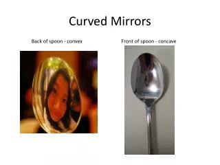
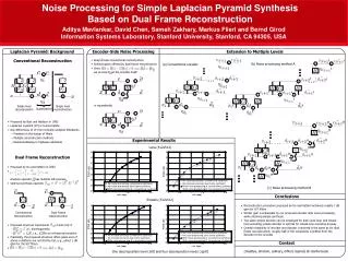
DEPTH FROM DISTORTION: PERFORMING 3D RECONSTRUCTION USING A CURVED MIRROR AND SINGLE CAMERA. DREXEL UNIVERSITY DEARTMENT OF MATHEMATICS ASST. PROF. ANDREW HICKS EMEK KOSE. Problem Statement. Compute 3D structure of the world from images. Usual approach: use two cameras and perform stereo.

E N D
DEPTH FROM DISTORTION: PERFORMING 3D RECONSTRUCTION USING A CURVED MIRROR AND SINGLE CAMERA DREXEL UNIVERSITY DEARTMENT OF MATHEMATICS ASST. PROF. ANDREW HICKS EMEK KOSE
Problem Statement • Compute 3D structure of the world from images. • Usual approach: use two cameras and perform stereo. • A single camera “stereo” approach using two mirrors was first considered by Nayar in 1988. • Our approach: consider how lines are distorted by a curved mirror.
Motivation For Our Method • Stereo is performed with multiple view of a point. An alternative: multiple views of an extended object (like cubism). m2 m1 The line of intersection of two planes Is the reconstruction of the straight line Whose image is the broken line on the Mirrors.
Curved Mirrors Have Multiple Viewpoints v4 • The two planar mirror method has the disadvantage that the line must cross the “break”. Also, some of the scene is missing. A curved mirror solves these problems. v3 v2 v1 Mirror ℓ IMAGE PLANE
Theorem For a spherical mirror, two points on the image plane have the same distance, r, to the optical axis if and only if the corresponding reflected lines intersect. By picking at least 4 image points, we can construct a quadratic system of equations determining the line. This allows for the 3D reconstruction of almost any line (from a single image). Main Theorem v1 Mirror v2 ρ ρ IMAGE PLANE
Given mirror shape f, and the point in the world (x, y, z), we calculate x and y component of rho, the distance of the image point from the optical axis. General Equation: [(df)^2-1]/2f = [z-f(rho)]/[r- rho] rho_x =rho . x/y, rho_y = rho. y/x. Reflected Ray: (rho_x, rho_y, f(rho_x, rho_y)+t.(x-rho_x, y-rho_y, z- f(rho_x, rho_y) For at least four points on the image plane, there exists only one line intersecting these four reflected lines. The condition for this is: q1= v1(t1) - v2(t2) q2= v1(t1) - v3(t3)q3= v1(t1) - v4(t4) Simultaneous solution of these 6 quadratic equations give us the intersection points. Sample Equations : -0.133 .s1+ 0.447 t1.s1 - 0.707 t2.s1 +0.229 - 0.447t1 + 0.832t3 = 00.028.s1 + 0.894 .t1. s1 - 0.707 t2.s1 - 0.062 - 0.894 t1 + 0.555t = 0-0.023.s1 - 1.101 t1. s1 + 0.866 t2.s1+ 0.049 + 1.101t1 - 0.675t3 = 0 -0.132 .s2+ 0.447t1.s2 - 0.707t2.s2 + 0.296 - 0.447t1 + 0.894t4 = 00.028. s2 + 0.894.t1.s2 - 0.707. t2. s2 - 0.093 - 0.894 t1 + 0.447 t4=0-0.023 .s2- 1.101 t1.s2 + 0.866t2.s2+ 0.073 + 1.101 t1 - 0.540 t4] = 0 Equations For General Approach
If we pick two pairs of points on the image of line such that each pair has the same magnitude, we can write linear equations for the reconstruction problem. The solution line is the intersection of two planes. Now least squares methods can be applied. A More Robust, Linear Approach v1 v2 v3 IMAGE PLANE v4
Results From Simulation Reconstruction of a line with the linear, least squares method. Checkerboard viewed by spherical mirror. The view of the checkerboard with a spherical mirror. The red line is an attempt to reconstruct the green line. The green line has depth -1, and the red line has depth -.7
Conclusion & Future Work • Single camera systems have many advantages over tradition stereo systems. For example our system, little calibration is needed. Additionally, correspondences between points do not have to be calculated. In our future work we will: 1. Perform error analysis 2. Look for optimal mirror shapes 3. Implement a real system