Download
1 / 37
370 likes | 533 Vues
MAGNETIZED FIBER ORIENTATION AND CONCENTRATION CONTROL IN SOLIDIFYING COMPOSITES. GEORGE S. DULIKRAVICH and Marcelo J. Colaço University of Texas at Arlington, Mechanical and Aerospace Eng. Dept., MAIDO Institute; UTA Box 19018; Arlington, TX 76019, USA dulikra@mae.uta.edu THOMAS J. MARTIN

E N D
MAGNETIZED FIBER ORIENTATION AND CONCENTRATION CONTROL IN SOLIDIFYING COMPOSITES GEORGE S. DULIKRAVICH and Marcelo J. Colaço University of Texas at Arlington, Mechanical and Aerospace Eng. Dept., MAIDO Institute; UTA Box 19018; Arlington, TX 76019, USA dulikra@mae.uta.edu THOMAS J. MARTIN Pratt & Whitney Engine Company, Turbine Discipline Engineering & Optimization Group; 400 Main Street, M/S 169-20; East Hartford, CT 06108, USA Seungsoo Lee Department of Aerospace Engineering, Inha University, Inchon, Korea
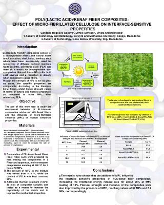
Defects in short fiber composites are often due to uncontrolled fiber orientation and concentration during composites manufacturing
In many applications it would be highly desirable to have directional dependence of physical properties of the material, that is, to have strongly non-isotropic materials.
It would be of interest to perform curing of the resin in such a way that the local concentration and orientation of the fibers is fully controlled.
During the solidification process, melt flow is generated due to strong thermal buoyancy forces. This process cannot be effectively controlled in the case of strong heat transfer, except if influenced by a global body force. One such body force is the general electromagnetic Lorentz force that is created in any electrically conducting fluid when either a magnetic field or an electric field is applied.
During the curing process in composites manufacturing, we usually work with electrically conducting liquid polymers and carbon fibers, although a variety of other molten substances and fibers made of other materials are often used. The resins are electrically conducting either because of the presence of iron atoms, salts, or acids.
If short carbon fibers (5-10 microns in diameter and 200 microns long) are vapor-coated with a thin layer (2-3 microns) of a ferromagnetic material like nickel, the fibers will respond to the externally applied electromagnetic fields by rotating and translating so that they become aligned with the magnetic lines of force (Hatta and Yamashita, 1988; Yamashita et al., 1989).
The objective of this work is to explore the feasibility of manufacturing specialty metal matrix and polymer composite materials that will have specified (desired) locally directional variation of bulk physical properties like thermal and electrical conductivity, modulus of elasticity, thermal expansion coefficient, etc.
The fundamental concept is based on specifying a desired pattern of orientations and spacing of micro fibers in the final composite material product. Then, the task is to determine the proper strengths, locations, and orientations of magnets that will have to be placed along the boundaries of the curing composite part so that the resulting magnetic field lines of force will coincide with the specified (desired) pattern of the micro fibers’ distribution.
The basic idea is that the fibers will align with the local magnetic lines of force (Hatta and Yamashita, 1988). It is important to understand that the pattern of these lines depends on the solidifying resin thermally and magnetically influenced flow-field and the spatial variation of the applied magnetic field.
The successful proof of this manufacturing concept involves the development of an appropriate software package for the numerical solution of the partial differential equation system governing magneto-hydro-dynamics (MHD) involving combined fluid flow, magnetic field, and heat transfer that includes liquid-solid phase change (Dulikravich, 1999).
It also involves development of a constrained optimization software that is capable of automatically determining the correct strengths, locations, and orientations of a finite number of magnets that will produce the magnetic field force pattern which coincides with the desired and specified fiber concentration and orientation pattern in the curing composite material part.
A Mathematical Model of Magneto-Hydro-Dynamics (MHD) With Solidification
Insulated Tc g0=9.81 m/s2 Th Insulated B4 (x) B1 (y) B2 (y) B3 (x) Geometry and boundary conditions for test cases 1 and 2.
Discretization of the magnetic field strength along the boundaries
Test case 1.In the inverse problem of determining the unknown magnetic field boundary conditions in test case 1 we used three parameters for B1(y) and three parameters for B3(x), while magnetic boundary conditions on the opposite walls were enforced as periodic, that is B2(1,y) = B1(0,y) and B4(x,1) = B3(x,0).
Specified and estimated boundary conditions for magnetic field in test case 1.
Specified and calculated magnetic and field distributions for test case 1.
Specified and calculated temperature field distributions for test case 1.
Convergence history for the hybrid optimization for test case 1.
Test case 2.In this case, B1(0,y) was approximated with only six parameters although the actual value was a discontinuous function. The value of B3(x,0) was similarly approximated with six parameters although the actual value was a constant. Magnetic boundary conditions on the opposite walls were enforced as periodic, that is B2(1,y) = B1(0,y) and B4(x,1) = B3(x,0).
Specified and estimated boundary conditions for magnetic field in test case 2.
Specified and calculated magnetic and field distributions for test case 2.
Specified and calculated temperature field distributions for test case 2.
Convergence history for the hybrid optimization for test case 2.
B4 (x) Tc B1 (y) B2 (y) g0=9.81 m/s2 B3 (x) Insulated Insulated x=0 Th(x) x=1 Geometry and boundary conditions for test case 3.
Test case 3.In this case, three separate parameters were used to parameterize each of the four magnetic boundary conditions, where and . That is, magnetic field boundary conditions were not explicitly treated as periodic. Vertical walls were adiabatic, top wall was isothermal, bottom wall had quadratically varying symmetric temperature distribution.
Specified and estimated boundary conditions for magnetic field in test case 3.
Specified and calculated magnetic and field distributions for test case 3.
Specified and calculated temperature field distributions for test case 3.
Convergence history for the hybrid optimization for test case 3.
DISCUSSIONIn this study, a number of assumptions were made concerning physics of the problem. For example, all physical properties were treated as constants instead of as functions of temperature. Transport equation for the passive scalar (concentration of the micro fibers) was not included, but could be added relatively easily (Hirtz and Ma, 2000). Its addition would enable us to predict and possibly control the distribution of the micro-fibers along the magnetic field lines of force. Thermal stresses in the accrued solid were not analyzed since such solids are by definition non-isotropic. Different options for treating the mushy region were not exercised (Poirier and Salcudean, 1986). Other, possibly more robust and accurate numerical integration methods were not explored (Fedoseyev et al., 2001; Dennis and Dulikravich, 2002) that could allow for physical values of the magnetic Prandtl number and for significantly higher values of viscosity used in the solid region.
Magnetization effects and fiber-resin interface drag were neglected. Also, possible effects of the material properties and the thickness and shape of the container walls were not included via a conjugate analysis (Dennis and Dulikravich, 2000). Finally, the current effort neglects the fact that the entire problem of having magnetizable micro-fibers orient themselves tangent to the prescribed magnetic field pattern is feasible only if the prescribed pattern is enforced in the moving and deforming mushy region. This mandates that the entire problem should in reality be treated as an unsteady control problem where boundary values of the magnetic field should vary in time. All of these details could and should be incorporated in the future work and compared to actual experimental results since this concept could be extended to manufacturing of three-dimensional composite objects and functionally graded objects of arbitrary shape.
Summary • Feasibility of a new concept has been demonstrated for manufacturing composite materials where micro fibers will align along a user-specified desired pattern of the magnetic lines of force. • This was accomplished by combining an MHD analysis code capable of simultaneously capturing features of the melt flow-field and the accrued solid, and a hybrid constrained optimization code. • The computed pattern of the magnetic lines of force was shown to closely replicate the specified pattern when the optimizer minimized the L2- norm of the difference between these two patterns. • This minimization process was achieved by optimizing a finite number of parameters describing analytically the distribution and the orientations of the boundary values of the magnetic field.