Download
1 / 29
410 likes | 1.3k Vues
Bipolar Junction Transistors. ET 212 Electronics . E lectrical and T elecommunication Engineering Technology Professor Jang. Acknowledgement.

E N D
Bipolar Junction Transistors ET 212 Electronics Electrical and Telecommunication Engineering Technology Professor Jang
Acknowledgement I want to express my gratitude to Prentice Hall giving me the permission to use instructor’s material for developing this module. I would like to thank the Department of Electrical and Telecommunications Engineering Technology of NYCCT for giving me support to commence and complete this module. I hope this module is helpful to enhance our students’ academic performance.
Objectives • Introduction to Bipolar Junction Transistor (BJT) • Basic Transistor Bias and Operation • Parameters, Characteristics and Transistor Circuits • Amplifier or Switch Key Words: BJT, Bias, Transistor, Amplifier, Switch ET212 Electronics – BJTsFloyd 2
Introduction A transistor is a device which can be used as either an amplifier or a switch. Let’s first consider its operation in a more simple view as a current controlling device. ET212 Electronics – BJTsFloyd 3
Basic Transistor Operation Look at this one circuit as two separate circuits, the base-emitter(left side) circuit and the collector-emitter(right side) circuit. Note that the emitter leg serves as a conductor for both circuits.The amount of current flow in the base-emitter circuit controls the amount of current that flows in the collector circuit. Small changes in base-emitter current yields a large change in collector-current. ET212 Electronics – BJTsFloyd 4
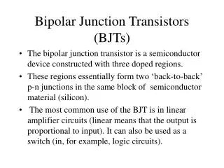
Transistor Structure The BJT (bipolar junction transistor) is constructed with three doped semiconductor regions separated by two pn junctions, as shown in Figure (a). The three regions are called emitter, base, and collector. Physical representations of the two types of BJTs are shown in Figure (b) and (c). One type consists of two n regions separated by a p regions (npn), and other type consists of two p regions separated by an n region (pnp). ET212 Electronics – BJTsFloyd 5
Transistor Currents The directions of the currents in both npn and pnp transistors and their schematic symbol are shown in Figure (a) and (b). Notice that the arrow on the emitter of the transistor symbols points in the direction of conventional current. These diagrams show that the emitter current (IE) is the sum of the collector current (IC) and the base current (IB), expressed as follows: IE = IC + IB ET212 Electronics – BJT Prof. Jang 6
Transistor Characteristics and Parameters Figure shows the proper bias arrangement for npn transistor for active operation as an amplifier.Notice that the base-emitter (BE) junction is forward-biased and the base-collector (BC) junction is reverse-biased. As previously discussed, base-emitter current changes yields large changes in collector-emitter current. The factor of this change is called beta(). = IC/IB The ratio of the dc collector current (IC) to the dc emitter current (IE) is the alpha. α = IC/IE ET212 Electronics – BJTs 7
Ex 3-1Determine βDC and IE for a transistor where IB = 50 μA and IC = 3.65 mA. IE = IC + IB = 3.65 mA + 50 μA = 3.70 mA ET212 Electronics – BJTsFloyd 8
Transistor Characteristics and Parameters Analysis of this transistor circuit to predict the dc voltages and currents requires use of Ohm’s law, Kirchhoff’s voltage law and the beta for the transistor. Application of these laws begins with the base circuit to determine the amount of base current. Using Kichhoff’s voltage law, subtract the .7 VBE and the remaining voltage is dropped across RB. Determining the current for the base with this information is a matter of applying of Ohm’s law. VRB/RB = IB The collector current is determined by multiplying the base current by beta. .7 VBE will be used in most analysis examples. ET212 Electronics – BJTs 9
Transistor Characteristics and Parameters What we ultimately determine by use of Kirchhoff’s voltage law for series circuits is that in the base circuit VBB is distributed across the base-emitter junction and RB in the base circuit. In the collector circuit we determine that VCC is distributed proportionally across RC and the transistor(VCE). ET212 Electronics – BJTsFloyd 10
Current and Voltage Analysis There are three key dc voltages and three key dc currents to be considered. Note that these measurements are important for troubleshooting. IB: dc base current IE: dc emitter current IC: dc collector current VBE: dc voltage across base-emitter junction VCB: dc voltage across collector-base junction VCE: dc voltage from collector to emitter ET212 Electronics – BJTsFloyd 11
Current and Voltage Analysis-continued When the base-emitter junction is forward-biased, VBE≅ 0.7 V VRB = IBRB: by Ohm’s law IBRB = VBB – VBE : substituting for VRB IB = (VBB – VBE) / RB: solving for IB VCE = VCC – VRc: voltage at the collector with VRc = ICRCrespect to emitter VCE = VCC – ICRC The voltage across the reverse-biased collector-base junction VCB = VCE – VBE where IC = βDCIB ET212 Electronics – BJTsFloyd 12
Ex 3-2Determine IB, IC, VBE, VCE, and VCB in the circuit of Figure. The transistor has a βDC = 150. IC = βDCIB = (150)(430 μA) = 64.5 mA IE = IC + IB = 64.5 mA + 430 μA = 64.9 mA When the base-emitter junction is forward-biased, VBE≅ 0.7 V IB = (VBB – VBE) / RB = (5 V – 0.7 V) / 10 kΩ = 430 μA VCE = VCC – ICRC = 10 V – (64.5 mA)(100 Ω) = 3.55 V VCB = VCE – VBE = 3.55 V – 0.7 V = 2.85 V ET212 Electronics – BJTsFloyd 13
Collector Characteristic Curve Collector characteristic curves gives a graphical illustration of the relationship of collector current and VCE with specified amounts of base current. With greater increases of VCC , VCE continues to increase until it reaches breakdown, but the current remains about the same in the linear region from .7V to the breakdown voltage. ET212 Electronics – BJT Prof. Jang 14
Ex 3-3Sketch an ideal family of collector curves for for the circuit in Figure for IB = 5 μA increment. Assume βDC = 100 and that VCE does not exceed breakdown. IC = βDC IB IBIC 5 μA 0.5 mA 10 μA 1.0 mA 15 μA 1.5 mA 20 μA 2.0 mA 25 μA 2.5 mA ET212 Electronics – BJTs 15
Transistor Characteristics and Parameters-Cutoff With no IB the transistor is in the cutoff region and just as the name implies there is practically no current flow in the collector part of the circuit. With the transistor in a cutoff state the the full VCC can be measured across the collector and emitter(VCE) Cutoff: Collector leakage current (ICEO) is extremely small and is usually neglected. Base-emitter and base-collector junctions are reverse-biased. ET212 Electronics – BJT Prof. Jang 16
Transistor Characteristics and Parameters - Saturation Once this maximum is reached, the transistor is said to be in saturation. Note that saturation can be determined by application of Ohm’s law. IC(sat)=VCC/RC The measured voltage across this now seemingly “shorted” collector and emitter is 0V. Saturation: As IB increases due to increasing VBB, IC also increases and VCE decreases due to the increased voltage drop across RC. When the transistor reaches saturation, IC can increase no further regardless of further increase in IB. Base-emitter and base-collector junctions are forward-biased. 17
Transistor Characteristics and Parameters- DC Load Line The dc load line graphically illustrates IC(sat) and Cutoff for a transistor. DC load line on a family of collector characteristic curves illustrating the cutoff and saturation conditions. Floyd 18
Ex 3-4Determine whether or not the transistors in Figure is in saturation. Assume VCE(sat) = 0.2 V. First, determine IC(sat) Now, see if IB is large enough to produce IC(sat). ET212 Electronics – BJTsFloyd 19
Transistor Characteristics and Parameters –Maximum Transistor Ratings A transistor has limitations on its operation. The product of VCE and IC cannot be maximum at the same time. If VCE is maximum, IC can be calculated as Ex 4-5A certain transistor is to be operated with VCE = 6 V. If its maximum power rating is 250 mW, what is the most collector current that it can handle? ET212 Electronics – BJTsFloyd 20
Ex 3-5The transistor in Figure has the following maximum ratings: PD(max) = 800 mW, VCE(max) = 15 V, and IC(max) = 100 mA. Determine the maximum value to which VCC can be adjusted without exceeding a rating. Which rating would be exceeded first? First, find IB so that you can determine IC. The voltage drop across RC is. VRc = ICRC = (19.5 mA)(1.0 kΩ) = 19.5 V VRc = VCC – VCE when VCE = VCE(max) = 15 V VCC(max) = VCE(max) + VRc = 15 V + 19.5 V = 34.5 V PD = VCE(max)IC = (15V)(19.5mA) = 293 mW VCE(max) will be exceeded first because the entire supply voltage, VCC will be dropped across the transistor. Floyd 21
The Transistor as an Amplifier Amplification of a relatively small ac voltage can be had by placing the ac signal source in the base circuit. Recall that small changes in the base current circuit causes large changes in collector current circuit. The ac emitter current : Ie≈ Ic = Vb/r’e The ac collector voltage : Vc = IcRc Since Ic≈ Ie, the ac collector voltage : Vc ≈ IeRc The ratio of Vc to Vb is the ac voltage gain :Av = Vc/Vb Substituting IeRc for Vc and Ier’e for Vb : Av = Vc/Vb ≈ IcRc/Ier’e The Ie terms cancel : Av ≈ Rc/r’e ET212 Electronics – BJTsFloyd 22
Ex 3-6Determine the voltage gain and the ac output voltage in Figure if r’e = 50 Ω. The voltage gain : Av≈ Rc/r’e = 1.0 kΩ/50 Ω = 20 The ac output voltage : AvVb = (20)(100 mV) = 2 V ET212 Electronics – BJTsFloyd 23
The Transistor as a Switch A transistor when used as a switch is simply being biased so that it is in cutoff (switched off) or saturation (switched on). Remember that the VCE in cutoff is VCC and 0V in saturation. ET212 Electronics – BJTsFloyd 24
Conditions in Cutoff & Saturation A transistor is in the cutoff region when the base-emitter junction is not forward-biased. All of the current are zero, and VCE is equal to VCC VCE(cutoff) = VCC When the base-emitter junction is forward-biased and there is enough base current to produce a maximum collector current, the transistor is saturated. The formula for collector saturation current is The minimum value of base current needed to produce saturation is ET212 Electronics – BJTsFloyd 25
Ex 3-7(a) For the transistor circuit in Figure, what is VCE when VIN = 0 V?(b) What minimum value of IB is required to saturate this transistor if βDC is 200? Neglect VCE(sat).(c) Calculate the maximum value of RB when VIN = 5 V. (a) When VIN = 0 V VCE = VCC = 10 V (b) Since VCE(sat) is neglected, (c) When the transistor is on, VBE≈ 0.7 V. VRB = VIN – VBE≈ 5 V – 0.7 V = 4.3 V Calculate the maximum value of RB Floyd 26
Troubleshooting Opens in the external resistors or connections of the base or the circuit collector circuit would cause current to cease in the collector and the voltage measurements would indicate this. Internal opens within the transistor itself could also cause transistor operation to cease. Erroneous voltage measurements that are typically low are a result of point that is not “solidly connected”. This called a floating point. This is typically indicative of an open. More in-depth discussion of typical failures are discussed within the textbook. ET212 Electronics – BJTsFloyd 27
Troubleshooting Testing a transistor can be viewed more simply if you view it as testing two diode junctions. Forward bias having low resistance and reverse bias having infinite resistance. ET212 Electronics – BJTsFloyd 28