Download

1 / 43
780 likes | 3.04k Vues
ERT 209 HEAT AND MASS TRANSFER FOR BIOPROCESS ENGINEERING Heat Exchangers. Heat transfer equipments: i) Heat exchangers ii) Evaporators iii) Dryers iv) Agitated vessel. Topic Outline. Types of heat exchangers Log Mean Temperature Different (LMTD) Correction Factor of LMTD

E N D
ERT 209HEAT AND MASS TRANSFER FOR BIOPROCESS ENGINEERINGHeat Exchangers
Heat transfer equipments: i) Heat exchangers ii) Evaporators iii) Dryers iv) Agitated vessel
Topic Outline • Types of heat exchangers • Log Mean Temperature Different (LMTD) • Correction Factor of LMTD • Heat Exchanger Effectiveness • Fouling Factors • Design of heat exchanger
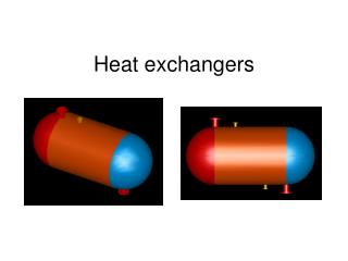
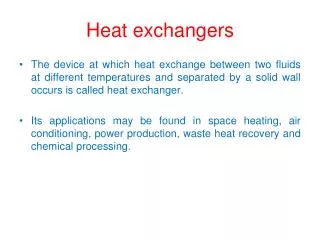
HEAT EXCHANGERS • Types of heat exchangers: 1. Double pipe heat exchanger 2. Shell and tube exchanger 3. Plate-type exchanger 4. Crossflow exchanger • The function of a heat exchanger is to increase the temperature of a cooler fluid and decrease that of a hotter fluid.
1. Double pipe heat exchanger • The simplest configuration (Fig 1.1) • One fluid flow through the inside pipe, and the second fluid flows through the annular space between the outside and the inside pipe. • The fluid can be in co-current or countercurrent flow. • Useful for small flow rates and when not more than 100 – 150 ft2 of surface is required.
2. Shell and Tube Exchanger • The most important type of exchanger in use in oil refineries and larger chemical processes and is suited for higher-pressure applications. • Useful for larger flow rates as compared to double pipe heat exchanger. • The simplest configuration: 1-1 counterflow exchanger (one shell pass and one tube pass) – refer to Figure 1.2. • consists of a shell (a large pressure vessel) with a bundle of tubes inside it. • One fluid runs through the tubes, and another fluid flows over the tubes (through the shell) to transfer heat between the two fluids.
Fig 1.2 Shell and tube heat exchanger (1 shell pass and 1 tube passes (1-1 exchanger)) • The cold fluid enters and flow inside through all the tubes in parallel in one pass • The hot fluid enters at the other end and flow counterflow across the outside the tubes in the shell side. • Cross-baffles – increase the shell side heat transfer coefficient
Fig 1.3 Shell and tube heat exchanger (1 shell pass and 2 tube passes (1-2 exchanger)) • The liquid on the tube side flows in two passes • The shell-side liquid flows in one pass • In the first pass of the tube side, the cold fluid is flowing counterflow to the hot shell-side fluid • In the second pass of the tube side, the cold fluid flows in parallel (co-current)
Fig 1.4 Shell and tube heat exchanger (2 shell pass and 4 tube passes (2-4 exchanger))
3. Plate heat exchanger • Use metal plates to transfer heat between two fluids • Consist of many corrugated stainless steel sheets separated by polymer gaskets and clamped in a steel frame. • The corrugation induce turbulence for improve heat transfer • The space between plates is equal to the depth of the corrugations (2 - 5 mm) • The plates are compressed in a rigid frame to create an arrangement of parallel flow channels with alternating hot and cold fluids. • Major advantage over a conventional heat exchanger in that the fluids are exposed to a much larger surface area because the fluids spread out over the plates.
4. Cross-flow exchanger • A common device used to heat or cool a gas such as air • One of the fluids, which is a liquid, flows inside through the tubes, and the exterior gas flows across the tube bundle by forced or sometimes natural convection. Fig. 1.7 Cross-flow heat exchangers: (a) one fluid mixed (gas) and one fluid unmixed; (b) both fluids unmixed.
The fluid inside the tubes is considered to be unmixed, since it is confined and cannot mix with any other stream. • The gas flow outside the tubes is mixed, since it can move about freely between the tubes, and there will be a tendency for the gas temperature to equalize in the direction normal to the flow. • For the unmixed fluid inside the tubes, there will be a temperature gradient both parallel and normal to the direction of flow. • A second type of cross-flow heat exchanger shown in Fig. 1.7(b) is typically used in air- conditioning and space-heating applications. • In this type the gas flows across a finned-tube bundle and is unmixed, since it is confined in separate flow channels between the fins as it passes over the tubes. The fluid in the tubes is unmixed.
Log Mean Temperature Difference (LMTD) Correlation Factors • For counter-current flow, LMTD for 1-1 exchanger with one shell pass and one tube pass is given by: Where: ΔTlm = log mean temperature difference ΔT1= T1 - t1 ΔT2 =T2 –t2 T1 = inlet shell-side fluid temperature T2 = outlet shell-side fluid temperature t1 = outlet tube-side temperature t2 = inlet tube-side temperature ΔT1 ΔT2 T1 t1 ----------------- Eq. (1) T2 t2 Temperature cross
For co-current flow, LMTD for 1-1 exchanger with one shell pass and one tube pass is given by: Where: ΔTlm = log mean temperature difference ΔT1= T1 - t1 ΔT2 =T2 -t2 T1 = inlet shell-side fluid temperature T2 = outlet shell-side fluid temperature t1 = inlet tube-side temperature t2 = outlet tube-side temperature ΔT1 ΔT2 ----------------- Eq. (2) T1 t1 T2 t2 Temperature cross
Exercise 1 A reaction mixture having a cpm = 2.85 kJ/kg.K is flowing at a rate of 7260 kg/h and is to be cooled from 377.6 K to 344.3 K. Cooling water at 288.8 K is available and the flow rate is 4536 kg/h. The overall Uo is 653 W/m2.K. • For counterflow, calculate the outlet water temperature and the area Ao of the exchanger. • Repeat for cocurrent flow
Correction of LMTD in Multipass Exchanger • Multipass exchangers have more tube passes than shell passes. • The LMTD as given in Eq (1 & 2) does not apply in this case and it is customary to define a correction factor, FT. • The relationship between LMTD and FT is define as below: Where is define as the correct mean temperature drop. • The general equation for heat transfer across surface of an exchanger is: ---------------- Eq. (3) ----------------- Eq. (4)
Figure 4.9-4 (Geankoplis, 4th ed.) shows the correction factor to LMTD for: a) 1-2 and 1-4 exchangers b) 2-4 exchangers • Two dimensionless ratios are used as follows: • Using the nomenclature of Eqs. (5 & 6), the of Eq. (1) can be written as: ----------------- Eq. (5 & 6) ---------------- Eq. (7)
Figure 4.9-4(a) Correction factor to LMTD for 1-2 and 1-4 exchangers (Geankoplis, 4th ed.)
Figure 4.9-4(b) Correction factor to LMTD for 2-4 exchangers (Geankoplis, 4th ed.)
Example 1Temperature Correction Factor for a Heat Exchanger A 1-2 heat exchanger containing one shell pass and two tube passes heats 2.52 kg/s of water from 21.1 to 54.4 0C by using hot water under pressure entering at 115.6 and leaving at 48.9 0C. The outside surface area of the tubes in the exchanger is Ao= 9.30 m2. a) Calculate the mean temperature different ΔTm in the exchanger and the overall heat transfer coefficient Uo. b) For the same temperatures but using a 2-4 exchanger, what would be the ΔTm? Solution: The temperatures are as follows: Thi= 115.6 0C Tho= 48.9 0C Tci = 21.2 0C Tco = 54.4 0C
Heat balance on the cold water, assume Cpm of water of 4187 J/kg.K and Tco – Tci = (54.4 – 21.1) 0C = 33.3 0C = 33.3 K q = mCpm(Tco – Tci) = (2.52)(4187)(54.4 – 21.1) = 348 200 W The log mean temperature difference using Eq. (1) is Calculate the Z and Y values using Eq (5 & 6)
From Figure 4.9-4(a), FT = 0.74 Using Eq. (3), Rearranging Eq. (4) to solve for Uo and substituting the known values, we have b) for 2-4 exchanger, refer to Fig. 4.9-4(b), FT = 0.94, Then, Hence, in this case the 2-4 exchanger utilizes more of the available temperature driving force.
Heat Exchanger Effectiveness – NTU Method • The LMTD is used in equation if the inlet and outlet temperatures of the two fluids are known and can be determined by a heat balance. • The surface area can be determined if U is known. • However, when the temperature of the fluids leaving the exchanger are not known, the tedious trial-and-error procedure is necessary. • To solve these cases, a method called the heat exchanger effectiveness is used which does not involve any of the outlet temperatures. • The Effectiveness – NTU (Number of Transfer Unit) method is a procedure for evaluating the performance of heat exchangers if heat transfer area, A and construction details are known .
----------- Eq. (8) • Heat balance for the cold (C ) and hot (H ) fluids is: • Calling , then CH > CC • Designate CC as Cminor minimum heat capacity. • If there is an infinite area available for heat transfer, TCo = THi , the effectiveness εis • If the hot fluid is the minimum fluid, THo = TCi , and ----------- Eq. (9) ----------- Eq. (10)
In both equations the denominators are the same and the numerator gives the actual heat transfer: • Note that Eq. (11) uses only inlet temperatures. • For the case of a single-pass, counterflow exchanger, combining Eqs (9 & 10): • We consider first the case when the cold fluid is the minimum fluid. Using the present nomenclature, ----------- Eq. (11) ----------- Eq. (12) ----------- Eq. (13)
----------- Eq. (14) • Combining Eq. (8) with the left side of Eq. (12) and solving for THi. • Subtracting TCo from both sides, • From Eq. (8) for Cmin= CC and Cmax = CH , • This can be rearranged to give the following: ----------- Eq. (15) ----------- Eq. (16) ----------- Eq. (17)
----------- Eq. (18) • Substituting Eq. (14) into Eq. (17), • Finally, substituting Eq. (15) and Eq. (18) into Eq. (13), rearranging, taking the antilog of both sides, and solving for ε, • We define NTU as the number of transfer unit as follows: • The same results would have been obtained if CH = Cmin ----------- Eq. (19) ----------- Eq. (20)
For parallel flow we obtain: • Figure 4.9-7 (Geankoplis, 4th ed.) shows the heat exchanger effectiveness, ε for a)counterflow exchanger – using Eq. (19) b)parallel flow exchanger – using Eq. (21) ----------- Eq. (21)
Figure 4.9-7 Heat exchanger effectiveness, ε: a)counterflow exchanger; b)parallel flow exchanger (Geankoplis, 4th ed.)
Example 2 Effectiveness of heat exchanger Water flowing at a rate of 0.667 kg/s enters a countercurrent heat exchanger at 308 K and is heated by an oil stream entering at 383 K at a rate of 2.85 kg/s (cp = 1.89 kJ/kg.K). The overall U = 300 W/m2.K and the area A = 15.0 m2. Calculate the heat transfer rate and the exit water temperature. Solution Assuming that the exit water temperature is about 370 K, the cp for water at an average temperature of (308 + 370)/2 = 339 K is 4.192 kJ/kg.K (Appendix A.2). Then (mcp)H = CH = 2.85(1.89 x 10³) = 5387 W/K and (mcp)C = CC = 0.667(4.192 x 10³) = 2796 W/K = Cmin. Since CC is the minimum, Cmin/Cmax= 2796 / 5387 = 0.519.
Using Eq. (20), NTU = UA/Cmin = 300 (15.0)/2796 = 1.607 Using Fig. 4.9-7(a) for a counterflow exchanger, ε = 0.71. Substituting into Eq. (11) q = ε Cmin (THi – TCi) = 0.71 (2796)(383 – 308) = 148 900 W Using Eq. (8), q = 128 900 = 2796 (TCo– 308) SolvingTCo = 361.3 K
Fouling Factors and Typical Overall U Values • After a period of operation, the heat transfer surface for a heat exchanger may become coated with various deposits present in the flow system, dirt, soot or the surface may become corroded as a result of the interaction between the fluids and the material used for construction of the heat exchanger. • Biological growth such as algae can occur with cooling water in the biological industries. • These deposits offer additional resistance to the flow of heat and reduce the overall heat transfer coefficient U. • To avoid or lessen these fouling problems, chemical inhibitors are often added to minimize corrosion, salt deposition and algae growth. • It is necessary to oversize an exchanger to allow for the reduction in performance during operation.
The effect of fouling is allowed for in design by including the resistance of the fouling on the inside and outside of the tube in Eq. (22). Where: hdi = fouling coefficient for inside of the tube (W/m2.K) hdo = fouling coefficient for outside of the tube (W/m2.K) • Fouling coefficients or fouling factors must be obtained experimentally by determining the value of U for both clean and dirty conditions in the heat exchanger. The fouling factor, Rf is define as: ----------- Eq. (22) ----------- Eq. (23)
Typical Fouling Coefficients is shown in Table 1 and the typical values of overall heat transfer coefficients are given in Table 2.Table 1 Typical Fouling Coefficients
Table 2 Typical Values of Overall Heat Transfer Coefficient in Shell and Tube Exchanger
Design of a Shell and Tube Exchangers Example 3 Design an exchanger to sub-cool condensate from a methanol condenser from 950C to 400C. Flow rate of methanol 100,000 kg/h. Brackish water will be used as the coolant with a temperature rise from 250C to 400C. The U for Brackish water is 600 W/m2.0C Solution Heat capacity of methanol, cp = 2.84 kJ/kg0C Heat water capacity, cp = 4.2 kJ/kg0C Use a split-ring floating head type. The bundle diametrical clearance = 68 mm Hence, shell diameter, Ds = 826 + 68 = 894 mm.
Use one shell pass and two tube passes, From Figure 4.9-4(a), FT = 0.85
Given, U = 600 W/m2.0C Provisional area, Choose 20 mm o.d., 16 mm i.d., 4.83 m long tubes (3/4 inch x 16 ft), cupro-nickel. Area of one tube Number of tubes, Nt As the shell-side fluid is relatively clean, use 1.25 triangular pitch. (The constants, K1 = 0.249 and n1 = 2.207)
Bundle diameter, Use a split-ring floating head type. The bundle diametrical clearance = 68 mm Hence, shell diameter, Ds = 826 + 68 = 894 mm.