Download
1 / 66
660 likes | 688 Vues
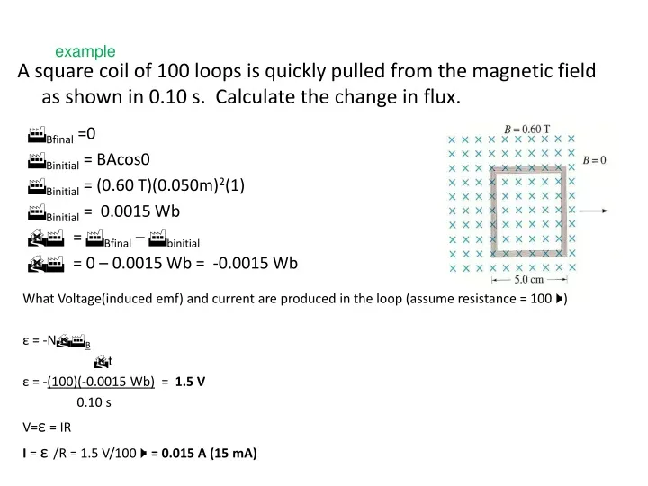
example. A square coil of 100 loops is quickly pulled from the magnetic field as shown in 0.10 s. Calculate the change in flux. F Bfinal =0 F Binitial = BAcos0 F Binitial = (0.60 T)(0.050m) 2 (1) F Binitial = 0.0015 Wb DF = F Bfinal – F binitial

E N D
example A square coil of 100 loops is quickly pulled from the magnetic field as shown in 0.10 s. Calculate the change in flux. FBfinal =0 FBinitial = BAcos0 FBinitial = (0.60 T)(0.050m)2(1) FBinitial = 0.0015 Wb DF = FBfinal – Fbinitial DF = 0 – 0.0015 Wb = -0.0015 Wb What Voltage(induced emf) and current are produced in the loop (assume resistance = 100 W) ε = -NDFB Dt ε = -(100)(-0.0015 Wb) = 1.5 V 0.10 s V=ε = IR I = ε/R = 1.5 V/100 W= 0.015 A (15 mA)
Ex ample An airplane travels at 1000 km/hr in a region where the earth’s magnetic field is 5 x 10⁻⁵T (vertical). What is the potential difference between the wing tips if they are 70 m apart? 1000 km/hr = 280 m/s E = Blv E = (5 X 10⁻⁵T )(70 m)(280 m/s) = 1.0 V
example Blood contains charged ions. A blood vessel is 2.0 mm in diameter, the magnetic field is 0.080 T, and the blood meter registers a voltage of 0.10 mV. What is the flow velocity of the blood? E = Blv v = E /Bl v = (1.0 X 10⁻⁴ V) = 0.63 m/s (0.080 T)(0.0020m)
Example Calculate the inductance of a solenoid with 100 turns, a length of 5.0 cm, and a cross sectional area of 0.30 cm2. L = m0N2A l L = (4p X 10-7 T m/A)(100)2(3 X 10-5m2) (0.05 m) L = 7.5 X 10⁻⁶ H or 7.5 mH
Chapter 33Alternating Current Circuits 33.1 AC Sources 33.2 Resistors in an AC Circuit 33.3 Inductors in an AC Circuit 33.4 Capacitors in an AC Circuit 33.5 The RLC Series Circuit 33.6 Power in an AC Circuit 33.7 Resonance in a Series RLC Circuit
33.1 AC Sources The output of an AC power source is sinusoidal and varies with time according to the following equation: Δv = ΔVmax sin ωt Δvis the instantaneous voltage ΔVmax is the maximum output voltage of the source Also called the voltage amplitude ω is the angular frequency of the AC voltage The angular frequency is ƒ is the frequency of the source T is the period of the source The voltage is positive during one half of the cycle and negative during the other half An AC circuit consists of a combination of circuit elements and a power source The power source provides an alternative voltage, Dv
A T Sine waves are characterized by the amplitude and period. The amplitude is the maximum value of a voltage or current; the period is the time interval for one complete cycle. The amplitude (A) of this sine wave is 20 V 50.0 ms The period is If the period is 50 ms, the frequency is 0.02 MHz = 20 kHz. The current in any circuit driven by an AC source is an alternating current that varies sinusoidally with time
A T Sine waves Sine waves are characterized by the amplitude and period. The amplitude is the maximum value of a voltage or current; the period is the time interval for one complete cycle. The amplitude (A) of this sine wave is 20 V 50.0 ms The period is
33.2 Resistors in an AC Circuit • Consider a circuit consisting of an AC source and a resistor • The AC source is symbolized by • ΔvR = Dv=Vmax sin wt • ΔvR is the instantaneous voltage across the resistor • The instantaneous current in the resistor is • The instantaneous voltage across the resistor is also given as ΔvR = Imax R sin ωt
The graph shows the current through and the voltage across the resistor The current and the voltage reach their maximum values at the same time The current and the voltage are said to be in phase • For a sinusoidal applied voltage, the current in a resistor is always in phase with the voltage across the resistor • The direction of the current has no effect on the behavior of the resistor • Resistors behave essentially the same way in both DC and AC circuits Phasor Diagram • To simplify the analysis of AC circuits, a graphical constructor called a phasor diagram can be used • A phasoris a vector whose length is proportional to the maximum value of the variable it represents
rms Current and Voltage • The average current in one cycle is zero • The rms current is the average of importance in an AC circuit • rms stands for root mean square • Alternating voltages can also be • discussed in terms of rms values The vector rotates counterclockwise at an angular speed equal to the angular frequency associated with the variable The projection of the phasor onto the vertical axis represents the instantaneous value of the quantity it represents
rms Current and Voltage • The average current in one cycle is zero • The rms current is the average of importance in an AC circuit • rms stands for root mean square • Alternating voltages can also be discussed in terms of rms values rms values are used when discussing alternating currents and voltages because AC ammeters and voltmeters are designed to read rms values
Example :For a particular device, the house ac voltage is 120-V and the ac current is 10 A. What are their maximum values? Irms = 0.707 imax Vrms= 0.707 Vmax
Example • A 60 W light bulb operates on a peak voltage of 156 V. Find the Vrms, Irms, and resistance of the light bulb. • Vrms = 110 V • Irms = 0.55 A • R = 202 Vrms = 156 V / 2 = 110 V Irms: P = IV 60 W = I (110V) .55 A P=V2/R 60 W = (110 V)2/R R = (110V)2/60W 202
Power • The rate at which electrical energy is dissipated in the circuit is given by • P = i2R • i is the instantaneous current • The heating effect produced by an AC current with a maximum value of Imax is not the same as that of a DC current of the same value • The maximum current occurs for a small amount of time • The average power delivered to a resistor that carries an alternating current is Example: Assume a sine wave with a peak value of 40 V is applied to a 100 W resistive load. What power is dissipated? Vrms = 0.707 x Vp = 0.707 x 40 V = 28.3 V 8 W
1- A heater takes 10 A rms from the 230 V rms mains. What is its power? • A) 1630 W • 2300 W • 3250 W • D) 4600 W 2- The voltage output of an AC source is given by the expression : v = (200 V) sin wt. Find the rms current in the circuit when this source is connected to a 100-Ωresistor.
33-3 Inductors in an AC Circuit • Kirchhoff’s loop rule can be applied and gives:
Current in an Inductor • The equation obtained from Kirchhoff's loop rule can be solved for the current • This shows that the instantaneous current iL in the inductor and the instantaneous voltage ΔvL across the inductor are out of phase by (p/2) rad = 90o
Phase Relationship of Inductors in an AC Circuit • The current is a maximum when the voltage across the inductor is zero • The current is momentarily not changing • For a sinusoidal applied voltage, the current in an inductor always lags behind the voltage across the inductor by 90° (π/2) Phasor Diagram for an Inductor • The phasors are at 90o with respect to each other • This represents the phase difference between the current and voltage • Specifically, the current always lags behind the voltage by 90o
Inductive Reactance • The factor ωLhas the same units as resistance and is related to current and voltage in the same way as resistance • Because ωdepends on the frequency, it reacts differently, in terms of offering resistance to current, for different frequencies • The factorXL is the inductive reactanceand is given by: XL = ωL
Inductive Reactance, cont. • Current can be expressed in terms of the inductive reactance • As the frequency increases, the inductive reactance increases • This is consistent with Faraday’s Law: • The larger the rate of change of the current in the inductor, the larger the back emf, giving an increase in the reactance and a decrease in the current
Example 33.2 A Purely Inductive AC Circuit In a purely inductive AC circuit, L = 25.0 mH and the rms voltage is 150 V. Calculate the inductive reactance and rms current in the circuit if the frequency is 60.0 Hz. What if the frequency increases to 6.00 kHz? What happens to the rms current in the circuit?
L = 0.6 H A V 120 V, 60 Hz Example : A coil having an inductance of 0.6 H is connected to a 120-V, 60 Hz ac source. Neglecting resistance, what is the effective current(Irms) through the coil? Reactance: XL = 2pfL XL = 2p(60 Hz)(0.6 H) XL = 226 W ieff = 0.531 A Show that the peak current is Imax = 0.750A
33.4 Capacitors in an AC Circuit • The circuit contains a capacitor and an AC source • Kirchhoff’s loop rule gives: Δv + Δvc = 0 and so Δv = ΔvC = ΔVmax sin ωt • Δvc is the instantaneous voltage across the capacitor q = C V [ V=Vmax sin(wt) ] • The charge is q = C ΔVmax sin ωt • The instantaneous current is given by • The current is p/2 rad = 90o out of phase with the voltage Take derivative: ic = dq/dt = C dV/dt
The current reaches its maximum value one quarter of a cycle sooner than the voltage reaches its maximum value The current leads the voltage by 90o Phasor Diagram for Capacitor • The phasor diagram shows that for a sinusoidally applied voltage, the current always leads the voltage across a capacitor by 90o
Capacitive Reactance • The maximum current in the circuit occurs at cos ωt = 1 which gives • The impeding effect of a capacitor on the current in an AC circuit is called the capacitive reactance and is given by
Voltage Across a Capacitor • The instantaneous voltage across the capacitor can be written as ΔvC = ΔVmax sin ωt = Imax XC sin ωt • As the frequency of the voltage source increases, the capacitive reactance decreases and the maximum current increases • As the frequency approaches zero, XC approaches infinity and the current approaches zero • This would act like a DC voltage and the capacitor would act as an open circuit
Quick Quiz Consider the AC circuit in the Figure .The frequency of the AC source is adjusted while its voltage amplitude is held constant. The lightbulbwill glow the brightest at; a)high frequencies b)low frequencies c)The brightness will be same at all frequencies.
C = 2 mF A V 120 V, 60 Hz Example :A 2-mF capacitor is connected to a 120-V, 60 Hz ac source. Neglecting resistance, what is the effective current through the coil? Reactance: XC = 1330 W ieff = 90.5 mA Show that the peak current is imax = 128 mA
Example What are the peak and rms currents of a circuit if C = 1.0 mF and Vrms= 120 V. The frequency is 60.0 Hz. XC = 1 = 1 2 p fC2p(60 Hz)(1.0 X 10⁻⁶F) XC = 2700 W Vrms = Vmax/√2 Vmax= Vrms√2 Vmax = (120 V)(√2) = 170 V Imax = Vmax/XC Imax = 170 V/2700 W Imax = 63 mA Irms= Vrms/XC Irms= 120 V/2700 W = 44 mA
Example A Purely Capacitive AC Circuit An 8.00μF capacitor is connected to the terminals of a 60.0-Hz AC source whose rms voltage is 150 V. Find the capacitive reactance and the rms current in the circuit What if the frequency is doubled? What happens to the rms current in the circuit? If the frequency increases, the capacitive reactance decreases—just the opposite as in the case of an inductor. The decrease in capacitive reactance results in an increase in the current. Let us calculate the new capacitive reactance
The RLC Series Circuit • The resistor, inductor, and capacitor can be combined in a circuit • The current and the voltage in the circuit vary sinusoidally with time
The RLC Series Circuit, cont. • The instantaneous voltage would be given by Δv = ΔVmax sin ωt • The instantaneous current would be given by i = Imax sin (ωt - φ) • φ is the phase angle between the current and the applied voltage • Since the elements are in series, the current at all points in the circuit has the same amplitude and phase
i and v Phase Relationships – Graphical View • The instantaneous voltage across the resistor is in phase with the current • The instantaneous voltage across the inductor leads the current by 90° • The instantaneous voltage across the capacitor lags the current by 90°
i and v Phase Relationships – Equations • The instantaneous voltage across each of the three circuit elements can be expressed as
More About Voltage in RLC Circuits • ΔVR is the maximum voltage across the resistor and ΔVR = ImaxR • ΔVL is the maximum voltage across the inductor and ΔVL = ImaxXL • ΔVC is the maximum voltage across the capacitor and ΔVC = ImaxXC • The sum of these voltages must equal the voltage from the AC source • Because of the different phase relationships with the current, they cannot be added directly
Phasor Diagrams To account for the different phases of the voltage drops, vector techniques are used Remember the phasors are rotating vectors The phasors for the individual elements are shown
Resulting Phasor Diagram • The individual phasor diagrams can be combined • Here a single phasor Imax is used to represent the current in each element • In series, the current is the same in each element
Vector Addition of the Phasor Diagram • Vector addition is used to combine the voltage phasors • ΔVL and ΔVC are in opposite directions, so they can be combined • Their resultant is perpendicular to ΔVR
Total Voltage in RLC Circuits • From the vector diagram, ΔVmax can be calculated
Impedance • The current in an RLC circuit is • Z is called the impedance of the circuit and it plays the role of resistance in the circuit, where • Impedance has units of ohms Phase Angle • The right triangle in the phasor diagram can be used to find the phase angle, φ • The phase angle can be positive or negative and determines the nature of the circuit
Determining the Nature of the Circuit • If f is positive • XL> XC (which occurs at high frequencies) • The current lags the applied voltage • The circuit is more inductive than capacitive • If f is negative • XL< XC (which occurs at low frequencies) • The current leads the applied voltage • The circuit is more capacitive than inductive • If f is zero • XL= XC • The circuit is purely resistive
Power in an AC Circuit • The average power delivered by the AC source is converted to internal energy in the resistor • av = ½ ImaxΔVmax cos f = IrmsΔVrms cos f • cos f is called the power factor of the circuit • We can also find the average power in terms of R • av = I2rmsR
Power in an AC Circuit, cont. • The average power delivered by the source is converted to internal energy in the resistor • No power losses are associated with pure capacitors and pure inductors in an AC circuit • In a capacitor, during one-half of a cycle, energy is stored and during the other half the energy is returned to the circuit and no power losses occur in the capacitor • In an inductor, the source does work against the back emf of the inductor and energy is stored in the inductor, but when the current begins to decrease in the circuit, the energy is returned to the circuit
Calculate the average power delivered to the series RLC circuit described in Example 33.5.
Example A circuit has R=25.0 W, L = 30.0 mH, and C = 12.0 mF. Calculate the impedance of the circuit if they are connected to a 90.0 V ac(rms), 500 Hz source. Also calculate the phase angle. XL = 2pfL XL = 2p(500 Hz)(0.030 H) = 94.2 W XC = 1/2pfC XC = 1/2p(500 Hz)(12 X 10-6F) = 26.5 W