Download
1 / 33
330 likes | 344 Vues
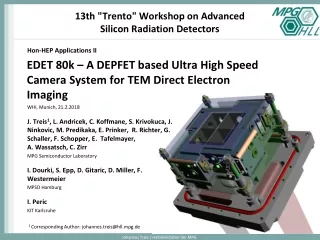
23rd International workshop on DEPFET Detectors and Applications. 80k Edet project Kloster Seeon 28.05.2019. Non-BELLE DEPFET: EDET. J. Treis, L. Andricek, M. Ibrahim, C. Koffmane,

E N D
23rd International workshop on DEPFET DetectorsandApplications 80k Edetproject KlosterSeeon 28.05.2019 Non-BELLE DEPFET: EDET J. Treis, L. Andricek, M. Ibrahim, C. Koffmane, S. Krivokuca, J. Ninkovic, M. Polovykh, M. Predikaka, E. Prinker, R. Richter, G. Schaller, F. Schopper, E. Tafelmayer, A. Vostrukhin, A. Wassatsch, C. Zirr MPG Semiconductor Laboratory I. Dourki, S. Epp, D. Gitaric, D. Miller MPSD Hamburg I. Peric KIT Karlsruhe
Contents • Introduction to the instrument • DEPFET pixels • ASM • Module structure • System structure • Small-size prototype • DMC Development • Summary Christian Koffmane / Halbleiterlabor der MPG
Introduction Stroboscopic imaging provides insight to the dynamics of processes Christian Koffmane / Halbleiterlabor der MPG
Introduction "Normal" imaging: • Continuous illumination w/ fixed intensity • Discrete, "gated" exposure by shutter • Exposure time defines image contrast • Tradeoff between image contrast and impact of motion blur • Defined by the dynamics of process "Stroboscopic" imaging: • Short, discrete illumination periods with high intensity (flashbulb) • Pulse intensity defines image contrast • Decouples exposure time, image contrast and motion blur • Frequency of illumination defines time resolution • Pulse duration defines impact of motion blur Christian Koffmane / Halbleiterlabor der MPG
Introduction Stroboscopic imaging in TEM world is challenging: • Real space imaging → High granularity • High intensity → High dynamic range • Direct electron detection → Thin substrate • High pulse frequency → High framerate • "Grey scale" image → No data reduction possible The instrument: • Detector FPA consisting of 4 individual, independent modules ("tiles") capable of stand-alone operation. • Small sensitivity gap between tiles (1.2 mm) • DEPFET arrays with 60 x 60 mm2 pixel size • Tile array size 512 x 512 pixels • 1 MPixel for complete FPA • Thinned substrate with 50 mm and 30 mm thickness • ASM complete with passives and FEE (DCD / DMC) • Readout in rolling shutter mode • Readout time 100 ns / row, 4 rows in parallel → 12.8 ms / frame • Framerate max. 80 kHz • FEE allows buffering of bursts (movies) with 100 frames • Maximum burst rate 100 Hz S. Epp: Introduction in E det 80k - motivation and requirements https://indico.mpp.mpg.de/event/4247/session/15/contribution/61/material/slides/0.pptx Christian Koffmane / Halbleiterlabor der MPG
Introduction Challenges: • Dynamic range • Single primary electron sensitivity • Primary electron @ 300 keV on 50 µm Si • → Distinguish 8k e- from noise • 50 (better 100) primaries per pixel to provide enough contrast • → 800k signal electrons to be stored in pixel • Multiple scattering: • Thin sensitive detector substrate • No support layer • Highly efficient beam dump for traversing electrons • Advanced thermal support • Operation in vacuum: • Small volume / extremely compact setup • Cooling / thermal stabilization • Data rate • Max. burst frequency 100 Hz ( 100 frames each) • Digitization with 8 bit resolution • Tile module data rate 2.9 GByte / s gross • Total data rate ~ 11.6 GByte /s gross • Data reduction / zero suppression difficult Christian Koffmane / Halbleiterlabor der MPG
Introduction Challenges: • Multiple scattering: • Deteriorates contrast • Thin sensitive detector substrate • Passive support contributes by backscattering • No support layer allowed • Advanced thermal support required • Highly efficient beam dump for traversing electrons necessary Passive support No support Christian Koffmane / Halbleiterlabor der MPG
DEPFET Pixel • DEPFET integrated amplifier • p-channel FET on depleted n-bulk • Signal charge collected in potential minimum below FET channel • "Internal gate", low capacitance & noise • FET current modulation ≥ 300 pA/el. • Reset via clear • Charge storage • Readout on demand • Rolling shutter mode EDET pixels: • Dynamic range problem • Implement signal compression in pixel • Overflow to source to tailor dynamic range Christian Koffmane / Halbleiterlabor der MPG
DEPFET Pixel EDET pixels: • Shape of source implant creates one overflow region • Large dynamic range • Sensor w/ integrated signal compression Drift DEPFET Gate (ext + int) Drain Source Clear Response curve (VDS = -5 V) Overflow regions No additional deep-n drift field by wedge shape full capacity Charge distribution (VGS = -3 V, VDS = -5 V) overflow Drain current (100 µA) Christian Koffmane / Halbleiterlabor der MPG Signal charge (Me-) Signal charge (Me-) Signal charge (Me-)
DEPFET Pixel Pilot devices showing expected results • signal compression • 290 pA/e- for the first 50k signal electrons • ~70 pA/e- for the rest • Dynamic range > 800k signal electrons • Operation window big enough to operate the large area device Full dynamic range explored with calibrated LED pulses. Christian Koffmane / Halbleiterlabor der MPG
Detector ASM ASM: • High integration density requires integration of Detector matrix, front-end ASICs and supporting passives on common substrate • "PCB on silicon" → All-Silicon module (ASM) • Substrate thinned down to 50 -30 µm thickness in sensor region • Supporting window bars up to 8 serial links (@320 Mbit /s) … Direct Current Digitizer (DCD-E) • UMC 130 nm technology • 256 channels read in parallel • 8 bit digitization, 100 ns conversion • 64 parallel data output links @ 320 MBit/s Switcher-B: • AMS H18 HV technology • Controller IC, 32 channels • Each channel driving gate and clear lines of 4 ASM pixel matrix rows in parallel DEPFET Movie Chip (DMC) • TSMC 40 nm technology • Data buffer, serializer & sequencer for all DCDs and Switchers • Fast data transfer to periphery using 8 parallel 320 Mbit /s LVDS outputs Christian Koffmane / Halbleiterlabor der MPG
Detector ASM JTAG Bias contacts Switcher Bank Pixel array 30.7 x 30. 7 mm2 Bondpads for DCD / DMC data & supplies Christian Koffmane / Halbleiterlabor der MPG Test pads (removed after met. 1 testing) Chip size ~ 50 x 38 mm2 DMC array DCD array (EDET specific DCD-E)
Module structure Module components: • ASM: All-Silicon module • Brick support: Thermomechanical support and interface to main heatsink • Patch panel: Wire bond adapter, local power conditioning and housekeeping circuitry • Total of 4 tile modules on main heatsink in vacuum vessel • Vacuum interface flange with flexible printed circuit for electrical connection • Module Interface circuitry for peripheral connection • Communication w/ control PC (housekeeping / online monitoring) using 1 GBit Ethernet interface • Trigger input from TEM and synchronization clock • Fileserver system for fast data storage, data transfer using 2 x 10 GBit optical interface (UDP stream) Christian Koffmane / Halbleiterlabor der MPG
System structure DAQ Concept: • Complete system is formed by 4 identical, independent tile modules • Configuration of modules via individual standard 1Gb Ethernet link • Control PC does configuration, housekeeping and online Monitoring • Trigger from TEM is applied to one ("master") module • Master distributes the trigger to slave modules using proprietary Inter-Module link (IML) • Fast data is transferred to module-individual Fileserver storage using 2 optical 10 Gbit Ethernet connections • Fileserver array makes data available for offline analysis • Possible replacement of module-individual configuration link by IML based master-slave architecture in a later stage Christian Koffmane / Halbleiterlabor der MPG
DLSP – Double L- shaped Patchpanel wirebond pads, decoupling capacitors, Temperature sensor • Symmetric layer stack up: 6 flex layers, 8 rigid layers • wirebond fan-out by through-hole and blind vias • 100 Ohm differential impedance on L6 and L8 with dedicated current return layers (no split plane) • 90° bend (number of bending cycles <10) • Moderate power dissipation on the rigid part (20W) • FPC to be used in vacuum, connected to cooling structure LDO voltage regulators for ASICs, housekeeping, SEAF8 connector
VIC • layer stack up: 5 flex layers, 2 rigid layers • Delivery scheduled for next week • Assembly needs to be further discussed and tested Vacuum flange adapters prototypes prepared
Module structure Module Interface circuitry (MIC) : • Peripheral interconnect based on modular stack of 3 modules • MSM: Service module hosting physical interfaces & interconnects • Housekeeping & configuration • Fast data transfer • Trigger inputs • Connectors for Mezzanine cards • MPM: Power module hosting pre-regulators and biasing circuits for ASM • Provides for supply of entire module w/ a single 12 V DC poser supply • MBM: Brain module based on powerful ZynqUltraScale FPGA from Xilinx • Service functions, fast data transfer using MGBTs and potential data compression and preprocessing MBM module (Enclustra Mercury + XU1) Christian Koffmane / Halbleiterlabor der MPG
Small-size prototype Christian Koffmane / Halbleiterlabor der MPG
Small-size prototype • Noise compare able to LMU PS • Next step: assembly small EDET matrix on E1 hybrid board Christian Koffmane / Halbleiterlabor der MPG
DMC Development • 200 DMCs arrived mid of January 2019 • Various chips have been tested using the DHP Probe Card and E1 Hybrid Boards (IDs #7, #8, #9 and #10) • All tested chips failed (JTAG configuration and fast control via TRG line) • Reason for the failure was found: wrong buffer was used in the Clock Tree Synthesis (CTS) • there was a warning message that there is no proper clock buffer in the library • still tool picked then a much too weak buffer • improve the design/layout and verification flow • Multi-mode Multi-Corner optimization (voltage, temperature, corners and parasitic load) • Timing annotated digital simulation • Power verification • External reviewer(s) Christian Koffmane / Halbleiterlabor der MPG
ASM – bare dies Christian Koffmane / Halbleiterlabor der MPG
ASM – populated dies Christian Koffmane / Halbleiterlabor der MPG
Summary & Outlook • ASM pilot production finished • Detector measurements on small devices done • Fabrication of main batch (8 + 4 wafers) has been resumed • Hardware preparation for tile module operation in progress • Commissioning of first tile modules with DHP in summer 2019 • Study of radiation hardness is in preparation • DMC Multi-mode Multi-Corner optimization ongoing, post-layout verification necessary • Concepts for full 80 kHz read-out under investigation – no data buffering Christian Koffmane / Halbleiterlabor der MPG
Thanks for your attention Christian Koffmane / Halbleiterlabor der MPG
Change of System Concept – the numbers Bottleneck on ASIC side The achievable data rate is strongly influenced by the total data rate. Depending on the system architecture, the overall data rate is limited by different bottlenecks. Sensor data rate per Quadrant: • 512 x 512 pixels per frame read out row wise @ 100 ns / row • 12.8 μs / frame DCD data rate: • Each DCD reads out 512 x 64 pixels per frame • DCD IC digitizes data @100 ns per row with 8 bit. • Volume per frame: 262 kbit • Transfer over 64 LVS lines @ 320 MHz to DMC DMC data rate: • Each DCD data stream is buffered by one DMC IC for a burst of 100 frames. • DMC transfers data to the peripheral readout components using a variable number of LVDS links • Speed at 320 Mbit / s or 160 MBit / s 1) Current configuration, 5th link (DHPT TX) could potentially be used, decreasing time by ~20 % 2) Theoretical value as defined by the DMC data transfer speed not including overhead data (checksums, frame # etc.) Decrease of ~ 10 % due to overhead data is to be expected Christian Koffmane / Halbleiterlabor der MPG
Modulation transfer function • Results of simulation for diverse substrate thickness values • Provides a quantitative description of the contrast behaviour Christian Koffmane / Halbleiterlabor der MPG
Radiation hardness MOS Operation window (100pe- limit) Real space detector sees a rather homogeneous radiation level → Oxide charge buildt up is homogeneous → compensated by Gate voltages Concern: inhomogeneous rad. Christian Koffmane / Halbleiterlabor der MPG
Scanning laser annealing Christian Koffmane / Halbleiterlabor der MPG
CAD impressions Cavity for beam dump Polysilicon brick • Beam dump geometry for lowest backscattering Patch Panel • Brick support w/ patch panel attached • Polysilicon for CTE-match Christian Koffmane / Halbleiterlabor der MPG
Hardware impressions Christian Koffmane / Halbleiterlabor der MPG
CAD impressions Insertion: • Insertion of complete FPA stack from below • No cable mounting from top required after insertion Main heatsink • Complete FPA (4 ASMs, FEE shield not shown) Christian Koffmane / Halbleiterlabor der MPG
CAD impressions Insertion: • Insertion of complete FPA stack from below • No cable mounting from top required after insertion Main heatsink Christian Koffmane / Halbleiterlabor der MPG
Detector Read-out • Row wise readout (Rolling Shutter) • The SwitcherB chip generates the control signals for the rows GATE and CLEAR • Readout chip processes all columns in parallel • DEPFET readout sequence (single sampling): • 1. select row with external gate • 2. readout transistor current • 3. clear charge from internal gate • 4. select next row DCD-E DMC Christian Koffmane / Halbleiterlabor der MPG