Download
1 / 20
200 likes | 390 Vues
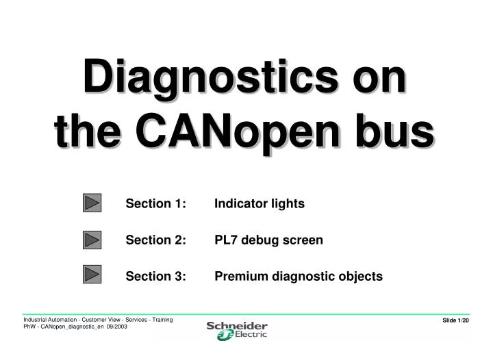
Diagnostics on the CANopen bus. Section 1: Indicator lights Section 2: PL7 debug screen Section 3: Premium diagnostic objects. In its recommendation DR-303-3, CiA advocates the use of diagnostic LEDs to identify problems relating to CANopen communication. The products can support either:

E N D
Diagnostics on the CANopen bus Section 1: Indicator lights Section 2: PL7 debug screen Section 3: Premium diagnostic objects
In its recommendation DR-303-3, CiA advocates the use of diagnostic LEDs to identify problems relating to CANopen communication. The products can support either: 2 mono-colour LEDs: Colour Full name Abbreviation Function GreenRUN LED CAN-RUN or RUN Node status (state machine) RedERROR LED CAN-ERR or ERR Error type 1 bi-colour LED: Colour Full name Abbreviation Function GreenSTATUS LED CAN-STATUS or CAN Node status(state machine) or red and error type Section 1: Indicator lights - 2 Recommendation DR 303-3 • Use of bi-colour LED: • In the event of conflict between green and red, red takes priority.
LED status and flashing intervals: Section 1: Indicator lights - 3 Recommendation DR 303-3
The CAN-RUN LED indicates the status of the product relative to the NMT start-up graph. Section 1: Indicator lights - 4 Operation of CAN-RUN LED
The CAN-ERR LED indicates the status of the physical layer of the product as well as any errors due to missing messages. Section 1: Indicator lights - 5 Operation of CAN-ERR LED • In the event of several simultaneous faults, the error with the highest number is indicated.
Section 1: Indicator lights - 6 Indicator lights on IA products
Section 1: Indicator lights - 7 CANopen master card TSXCPP100
Section 1: Indicator lights - 8 CANopen communication card for ATV58: VW3A58308 Green LED = OK Yellow LED = COM
CANopen CAN-ERR RUN TX Overflow RW Section 1: Indicator lights - 9 CANopen communication module for TEGO POWER/QUICKFIT The first 4 LEDs relate to CANopen communication
I/O RUN I/O ERR Section 1: Indicator lights - 10 CANopen communication module for TEGO POWER/QUICKFIT The last 2 LEDs relate to the module and the I/O Error table
Section 2: PL7 debug screen - 11 Implicit diagnostic objects
2 bits: %Iy.MOD.ERR: module fault %Iy.1.ERR: channel fault 24 words: %IWy.1.0 to %Iwy.1.23 indicating: the channel status the last error code for the module the master module status the last slave that generated an error code and its address in the error counters the status of the various slaves (1 to 126) the availability of diagnostic information for each slave Section 3: Premium diagnostic objects - 12 Implicit diagnostic objects
Section 3: Premium diagnostic objects - 13 Detailed description of implicit diagnostic objects
Section 3: Premium diagnostic objects - 14 Detailed description of implicit diagnostic objects
Section 3: Premium diagnostic objects - 15 Detailed description of implicit diagnostic objects
Section 3: Premium diagnostic objects - 16 Detailed description of implicit diagnostic objects
Searching for a fault on the CANopen bus is carried out in the following sequence with a growing level of precision: Diagnostic indicator lights on master and slaves Use of implicit diagnostic objects See flow chart on next slide Transmission of a SEND_REQ diagnostic command to the slave or slaves concerned Section 3: Premium diagnostic objects - 17 Diagnostic methodology
Section 3: Premium diagnostic objects - 18 Diagnostic methodology Master in local or stop mode NO %IWy.1.3 MSB = 0x00 or 0x40 ? YES No fault on master? Rectify the fault identified NO %IWy.1.3 LSB = 0 ? YES If start-up by program mode Set %QWy.1.0:X0 Start up bus Master in RUN mode? NO Run diagnostics on inactive slaves %IWy.1.3 MSB = 0x40 ? SEND_REQ 0x31 and rectify the fault identified YES NOK Check active slaves Test %IWy.1.8 to %IWy.1.15 OK
Section 3: Premium diagnostic objects - 19 Diagnostic methodology If start-up by program or semi-automatic start-up mode Set %QWy.1.0:X0 Check activation of I/O exchange Normal operation Card fault? %Iy.1.ERR = 1 ? NO X8 = 1: Configuration error Look for error code in %IWy.1.1 and %IWy.1.2 X9 = 1: PDO transfer error Contact Schneider support X10 = 1: SDO transfer error Look for error code in %IWy.1.1 and %IWy.1.2 X11 = 1: PCMCIA card fault Look for error code in %IWy.1.1, %IWy.1.3 and %Iwy.1.4 X12 = 1: Bus hardware fault (check wiring) Check bus error and bus stop counters X13 = 1: Slave fault Check error source in %Iwy.1.4 + send diagnostic request X14 = 1: Fault - output in fallback position Check that PLC is in RUN mode and check %QWy1.0 X15 = 1: New diagnostics available Identify slaves concerned %Iwy.1.16 to %Iwy.1.23 + send diag. request Fault detected YES Test card status word %IWy.1.0 Precise identification of fault and correction
Section 3: Premium diagnostic objects - 20 Accessing explicit diagnostic variables (* Updating of variable %MW0.1.2 *) IF %MW200=1 THEN READ_STS %CH0.1; END_IF; ! (* Reading of explicit DIAGNOSTIC exchange words*) (*Address ADR#0.1.SYS Type of diagnostic object : %MW3301 1 to 127 = slave diagnostics 128 = master card diagnostics 130 = message exchange error history Start address in diagnostic table: %MW3302 Length of diagnostic to be read : %MW3303 Reception table : %MW3310:20 Report of exchange : %MW3350:4 *) IF %MW3300=1 AND NOT %MW3350:X0 THEN %MW3300:=0;%MW3353:=6; SEND_REQ(ADR#0.1.SYS,16#0031,%MW3301:3,%MW3310:20,%MW3350:4); END_IF;