Download
1 / 21
210 likes | 272 Vues
Field of the radiation from a foil of oscillating charges. We now will have to integrate over the whole plane of charges (the foil) the fields that they irradiate.

E N D
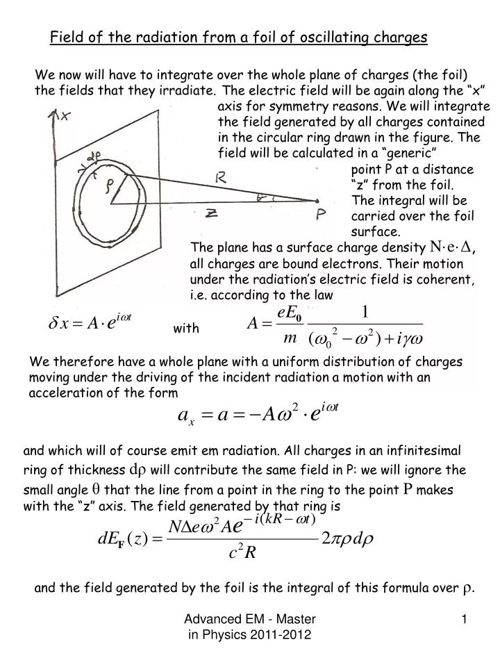
Field of the radiation from a foil of oscillating charges We now will have to integrate over the whole plane of charges (the foil) the fields that they irradiate. The electric field will be again along the “x” axis for symmetry reasons. We will integrate the field generated by all charges contained in the circular ring drawn in the figure. The field will be calculated in a “generic” point P at a distance “z” from the foil. The integral will be carried over the foil surface. The plane has a surface charge density N·e·Δ, all charges are bound electrons. Their motion under the radiation’s electric field is coherent, i.e. according to the law with We therefore have a whole plane with a uniform distribution of charges moving under the driving of the incident radiation a motion with an acceleration of the form and which will of course emit em radiation. All charges in an infinitesimal ring of thickness dρwill contribute the same field in P: we will ignore the small angle θ that the line from a point in the ring to the point P makes with the “z” axis. The field generated by that ring is and the field generated by the foil is the integral of this formula over ρ. Advanced EM - Master in Physics 2011-2012
which is valid for Z>0. We now will replace A with is value from the eq. of motion of the charges, ignoring for now the dissipative term γ. We obtain for the field emitted by the foil electrons the value (which we call EF , the field emitted by the foil) the formula A simplification of the integral comes by noticing that since And we can replace by R· dR in the integral, thus dropping the R term in the denominator. We are now left with the integral: This result is not a result since it has a serious problem: the term oscillates continuously for R ∞ and therefore is not defined. One argument that has been put forward is that since it oscillates its contribution averages to zero and therefore: There is a better argument to obtain the same result , which is found in Feynman 1, 30-11, and is given in the next two pages. We assume this term to be zero, add the time dependence we obtain: Where Es is as shown in lesson 21, p. 13. Advanced EM - Master in Physics 2011-2012
What does the integral mean? The symbol stands for the sum of small segments (in the complex plane) of length dR and phase θ= kR (see drawing). When we move away from the center of the integration ring (ρ increases) the value of the integral turns indefinitely around on the circumference shown in the next figure. When the infinitesimal segments summed in the integral add up, each segment has an angle kΔR with the preceding segment. The curve traced by the integral as the upper limit tends to ∞ is a circle Real axis with center Imaginary axis As it often happens in these cases, pushing the integral to infinity without any convergence mechanism in the equations is a procedure correct from the mathematical point of view but not physically.There are physical reasons why the integral can not oscillate with the same amplitude all the way to infinity; for example, a cos(θ) factor due to the “transverse acceleration” causing the radiation field; and, the other fact that there is not such a thing as a plane wave all the way to infinity. All these factor cause the second term in the calculation of the integral, i.e.. to be zero. Advanced EM - Master in Physics 2011-2012
The integral, as R increases, goes around the circle and turns around indefinitely. The value of the whole integral as we increase the radius runs a spiral curve which eventually tends to the circle center. But – as R increases the radius of the integrated ring gets larger and larger and the contributed field gets smaller and smaller and the integral runs along a spiral, which eventually ends at the spiral’s center, Advanced EM - Master in Physics 2011-2012
We can, now that we have obtained it, compare this formula that we have obtained for a foil of bound electrons (transparent material), with the one we expected from the experimental study of the behaviour of light incident on transparent matter (see lesson 21, p.12): we compare Light through transparent foil radiation from sheet electrons And obtain the result that the two equations are equal if • So, the model yields a formula for the effect of the foil that not only gives the right effect ( a retardation of the phase wrt to the free incident wave), but also explains its origin and allows us to calculate the index of refraction. In fact, we have: • Understood why the radiation moves with a phase velocity lower than c in transparent materials. • Obtained a formula which allows us to connect the index of refraction to other measurable parameters of matter, such as electron densities and emission frequencies. • We understand also the dispersion of the index of refraction, i.e. its dependence on the light’s frequency. Advanced EM - Master in Physics 2011-2012
Since bound electrons in matter have different resonance frequencies, the equation for the index of refraction is modified to take into account all those frequencies: Where the fi are the fraction of the atom electrons that have that resonance frequency. For most frequencies, n increases as the frequency increases. Only near the resonance frequencies does n decrease, an effect called anomalous dispersion. (as a rule, a prism deflects more the higher frequencies. In presence of anomalous dispersion it is the other way around). Also, near the resonance frequencies, where the term can become very small, the term iγω becomes important. It has the effect of making the index of refraction a complex number, n = n’ -i·n” As a consequence in the formula for the outgoing wave appears a multiplying term of type i.e. an absorption of the incident wave inside the foil (of thickness Δ). We have seen how the motion of the electrons radiates a field in the forward direction. There is no reason why this radiation should not be emitted in the backward direction as well: it is called the “reflected wave”. The reflected wave is equal to thewave emitted by the foil in the forward direction: only difference is the propagation direction; in the formulas, the exponent sign of the space dependence is: “+ikr”. Advanced EM - Master in Physics 2011-2012
In summary, the radiation fields are emitted by the foil, one wave forward and the other backwards. They travel with velocity “c” and have the same polarization as the incident wave. Their amplitudes and phases are: For z>0 For z<0 The two waves emitted by the foil are equal in amplitude and frequency (and in phase at the origin). The one emitted forward adds to the impinging external radiation with a phase difference of 90 degrees. The wave emitted bacwards travels back but is far less intense than the incoming wave: the motion of the electrons under the effect of the radiation’s electric field is limited by the electrons being bound to the nucleus. Advanced EM - Master in Physics 2011-2012
Rayleigh scattering and the diffusion of light In the computing of the interaction of light with matter we made a simplification which is not always valid: it was considered that the surface density of electrons was so high that light was emitted only forward and backward, but not at different angles because there the fields emitted by the charges left or right, up or down were compensated by equal fields out of the forward region emitted by the other electrons. This is certainly the case in solids and liquids. It is less so in gases, especially rarefied gases P. ex. high atmosphere. The gas is a distribution of radiant systems (molecules, dust, ….) each of small size compared to the wavelength of the incident radiation (ex.: Sun’s light) which excites on that dust and on these molecules electric and magnetic multipoles. Which multipoles are excited depends, of course, on the characteristics of the molecules etc: in most cases in fact it is dipoles. They oscillate in phase with the incoming radiation and as consequence radiate em energy in all directions, with an angular distribution that we know. If we have a regular and dense distribution of the diffusion centers, which also oscillate and emit in phase, the amplitudes of the emitted waves add up in phase only in the forward direction. In the case instead of a completely random distribution of the diffusion centers what adds up are not the amplitudes but the intensities. We have already calculated the intensity of the diffused radiation as a function of the frequency for bound electrons It turns out that in the atmosphere ω0²>>ω² and the cross-section gets: Advanced EM - Master in Physics 2011-2012
Owing to the dependence of the cross-section on the light wavelength λas 1/ λ4 the violet light (~410 nm) is diffused a factor 6 more than the red light(~600nm). This is the reason why the sky is blue (when the sun is at the zenith): we see coming from all the sky the blue light which has been diffused towards our eyes by the atmosphere all around. And the reason why the sun and the sky around it are red at sunset: the light from the sun crosses the atmosphere at grazing angle, and goes through a much longer amount of atmosphere than when the sun is above us. The blue light is totally scattered away, and only the red light coming straight to the observer is left undisturbed. In NTP conditions the absorption lengths of the atmosphere for respectively violet, green and red light are 30, 70 and 188km. Advanced EM - Master in Physics 2011-2012
Interaction of light with matter: the case of a foil of conducting material. Consider again the foil of material perpendicular to the direction of an incident plane wave, already treated for an insulator, but this time with a conductor. The key point in the treatment is to model the movement of the electrons in presence of an external electric field. In the case of a conductor, what the electrons do is well modeled by an old, well known law: Ohm’s law! The conductor has volume conductivity σand the current density is . For the case of our foil hit by this radiation the current density is (the light being linearly polarized, with the electric field along the “x” axis). The vector potential AFradiated by such current (reduced to surface current jxΔ) is obviously aligned along the “x” axis A={AX,0, 0} and it can be calculated with the formula for the retarded potentials – in this case simplified because we are studying a case of harmonic time dependence: Reflected wave Advanced EM - Master in Physics 2011-2012
It is easy to get EF and BFonce AF is known (the e.s. potential Φ is zero, since ρ=0): AF being parallel to the current, and therefore along the “x” axis, so is EF). AF being moreover only dependent on “z”, as well as parallel to “x” , the only non-null component of B will be BFy. SO FAR, we have not done anything really new wrt what done for the glass foil. We have proceeded in a new way, that we did. We started by computing the vector potential instead of writing the electric field. And, we have calculated also the magnetic field. But we are basically still in the same area. And also all the formulas we found for the case of the glass foil can be derived from these ones by simply remembering that The transparent case can therefore be dealt with by introducing an imaginary or complex conductivity σ. Advanced EM - Master in Physics 2011-2012
Since in the formulas for the fields that we just obtained the conductivity is a multiplying factor, the fields emitted by the insulating foil are 90° out of phase with the incoming radiation –which explains the phase retardation.. Moreover, since the electrons are bound, their motion will be limited, and so will be limited their acceleration and in the end the emitted fields will not be large, much smaller actually than the incident field E0. In the case of a conductor however, if the conductivity is sufficiently large, the field emitted by the foil (of opposite direction wrt the incoming field), which subtracts from it in the forward-going wave can be of comparable amplitude after a very short distance Δ, thus ultimately reducing to zero the forward-going radiation: it is the absorption of light . So far, all is rather clear and understandable. But, we still are considering only slabs, foils extremely thin. • Now we want to do the thing exactly, study the passage of radiation through thick slabs of material. What we have to do is now to take into account, in the calculation of the motion of the electrons, also the fields emitted by the other electrons. There are two contributions from these electrons: those upstream of the test point will contribute with their wave emitted forward, while thosedownstream will contribute with the reflected wave. • The physical system we will study is that of a plane wave travelling towards the right in vacuum, until it hits a semi-infinite slab of conducting material. What we want to calculate is the field at a given point inside the material, at a definite value of “z”. • The way to do this calculation is the following: we divide the material in thin foils, for which we know the emitted field; in one of these foils is the point P, with coordinate “z”, where we calculate the fields. • To the fields in P three terms contribute: • The incident field Es; • The sum (integral) of the fields radiated forward by the foils upstream of P: an integral of the forward wave from 0 to z. • The sum (integral) of the fields radiated backwards by the foils downstream of P: an integral of the fields from z to∞ . Advanced EM - Master in Physics 2011-2012
And a similar equation for B. These equations look fairly horrible. To make them (the last one) easier, much easier we need to derive both sides twice wrt “z”in order to obtain: And a similar equation for B. Now, this equation is very easy to solve. It could have been found starting from the Maxwell equations, just replacing J withσE. But this derivation has a much more direct physical meaning. The equation has two possible solutions: Advanced EM - Master in Physics 2011-2012
The physics is in these two equations. In the complex plane, the square roots in the exponents lay in the first quadrant, because the expression under the root sign lay in the 2nd one, very near the imaginary axis. Therefore both the imaginary and the real part of the exponent lay in the first quadrant (for the case of the “plus” sign in the exponent), and have nearly the same amplitude (see below). Of the two solutions, the physical one is : which corresponds to a wave being absorbed. The amplitudes A are found by inserting the solutions in the differential equation and equating the terms. It turns out that • At this point we may insert some number! • The conductivity of aluminum is ~3.5x10⁷ mho/m which, in Gaussian units is 9x10⁹ s-1. Putting all numbers together, for visible light To be compared with, for aluminum, Then: Advanced EM - Master in Physics 2011-2012
For metals and visible lights we can neglect k wrt 4πσ/c, (a factor ~1000 between the two) and also With these approximations we obtain: • Both E and B decrease exponentially in amplitude entering in the conductor with a decay constant sqrt(2πkσ), which is called the skin depth and is smaller than a wavelength of visible light. • In the conductor the magnetic field is larger than the electric field by a factor sqrt(4πσ/ω). • The reflected wave can be computed easily because now we know the total electric field which acts on the electrons. Nearly all the incident wave is reflected! The reason is that in the conductors the conductivity σis high, and the electronsmove fast, much faster than that small adjustment of the orbits in the case of the bound electrons. They have sufficient time in a period to reach high speeds, i.e. large average accelerations and therefore large emitted fields –which have opposite sign wrt the incoming radiation. Advanced EM - Master in Physics 2011-2012
Interaction of radiation with matter ( i.e. with charges): last remarks • In the last lesson we have studied the passage of radiation through matter. Three cases have been considered: • We used the equations of motion of electrons bound in atoms to calculate their velocity and acceleration when they are subject to the electric field of an incoming radiation. The first case studied was that of TRANSPARENT, homogeneous material, which is also non-conducting. The radiation had been taken as a sinusoidal function of time. It was found that the TOTAL field, - i.e. the sum of the impinging radiation pus the wave generated by the oscillating electrons - for a simple, linearly polarized plane wave incident on a thin foil of transparent material accounted for a slower phase velocity of the light in the foil (which is seen experimentally) and also yielded a formula for the material’s index of refraction. • We then studied the case of a CONDUCTIVE thin foil. In such case we have not used the equations of motion of the bound electrons to calculate the emitted radiation but more simply the Ohm’s law. • We have then extended that treatment to account for the passage of the radiation through a thick, semi-infinite layer of conductor. We have then found that inside the transparent, non-conducting foil the field oscillates with the same angular frequency as the incoming radiation, BUT that the wave generated by the small oscillations of the bound electrons is 90 degrees out of phase wrt the incident wave, therefore causing an apparent phase delay in the transmitted one. Advanced EM - Master in Physics 2011-2012
We have also found that in the conductor THE FIELD from the electrons can be much larger that what it is in an insulator (transparent), In such case the wave emitted by the electrons has opposite phase (or the same phase but negative amplitude) wrt the incident one, thus subtracting from it and quickly bringing it to nearly zero; and efficiently moving (nearly) all its energy to the reflected wave. The transmitted wave in a conductor has the form • which corresponds to an absorbed wave (the exponent is a complex number). In the formula, • σ is the metal’s conductivity, and • kis the radiation’s wave number. • For aluminum and visible light, at λ~500 nm we have: • The coefficient of the exponent is then: Advanced EM - Master in Physics 2011-2012
We have seen in the previous page the dependence of the radiation electric field on the depth “z” inside the conductor - which then, of course, has to be multiplied by the time dependence. That space dependence is determined by the differential equation: Now, that coefficient , whose square root multiplied by “z” is the exponent in the field’s formula, is a complex number. Its square root is therefore also a complex number. The coefficient has a positive imaginary number and a negative (but much smaller than the imaginary) real number. Its representation is therefore in the second quadrant, very near the imaginary axis. And its square root has an amplitude square root of its amplitude and a phase of about 45 degrees: real and imaginary parts about equal, the number is in the first quadrant. Its amplitude is approximately with about equal real and imaginary parts The solution of E(z) is then the product of two exponentials, The first exponential is a decay with characteristic length Advanced EM - Master in Physics 2011-2012
But… Then Since then and the field decays exponentially inside the conductor, with a decay length much shorter than one wavelength. Then, if and how rapidly the incoming wave is absorbed inside the conductor depends on the relative values of σand k, the wavelength of the incident radiation and on the conductivity, i.e. how many free electrons are per unit volume and how fast they move. Of course, the fact that the conductivity σis so large in metals has the consequence that the incoming wave is absorbed in a distance much smaller than a wavelength. Advanced EM - Master in Physics 2011-2012
The index of refraction revisited Having done the work of calculating the field in a thick slab of conductor, we can recycle the obtained result for the case of a thick slab of transparent material. In solving for the conductor case we used the fact that the velocity of the electrons is proportional to the electric field with coefficient σ . We can apply the results obtained to the bound electron case by using the “conductivity” obtained from the equation of motion of the bound electrons: In this case the electrons velocity is also proportional to the electric field, but with a complex conductivity. For a transparent thick slabwe can therefore use the formulas obtained for the thick conductor using for the conductivity the value: The two solutions found are: Advanced EM - Master in Physics 2011-2012
Since the root will have a positive real part only the solution with the minus sign in front of the square root is physical. If we insert it in the differential equation we find the results for E(z,T): Valid for z>0 Valid for z<0 In these equations the value of “n”, the index of refraction, corresponds to the formula: This is a very useful formula. But it is not what we found a few pages ago…. It turns out that this second formula, which we got out from the treatment of a thin foil, is an approximation – for thin foils - of the exact formula. Advanced EM - Master in Physics 2011-2012