Download
1 / 28
280 likes | 417 Vues
The Status of the CMS Electromagnetic Calorimeter. R M Brown On behalf of the CMS ECAL Community. Overview. Introduction Design objectives and technology choices Description and status: Crystals Photo-detectors On-detector electronics Off-detector electronics

E N D
The Status of the CMS Electromagnetic Calorimeter R M Brown On behalf of the CMS ECAL Community Split 08/09/04 R M Brown - RAL 1
Overview • Introduction • Design objectives and technology choices • Description and status: • Crystals • Photo-detectors • On-detector electronics • Off-detector electronics • Laser monitoring system • Mechanical construction and assembly • Pre-shower • Test beam results • Calibration strategy • Construction and installation schedule • Summary Split 08/09/04 R M Brown - RAL 2
HCAL Muon chambers Tracker 4T solenoid ECAL Iron yoke Compact Muon Solenoid Total weight:12,500t Overall diameter:15m Overall length:21.6m Magnetic field:4T Split 08/09/04 R M Brown - RAL 3
High resolution electromagnetic calorimetry is a central design feature of CMS Benchmark process: H m /m = 0.5[E1/E1 E2/E2 / tan(/2)] Where:E/E = a/E b c/E Aim: Barrel End cap Stochastic term: a= 2.7% 5.7% (p.e. stat, shower fluct, photo-detector, lateral leakage) Constant term: b= 0.55% 0.55% (non-uniformities, inter-calibration, longitudinal leakage) Noise: Low Lc= 155MeV 770MeV High L210MeV 915MeV (dq limitedbyinteractionvertex measurement) L=1034cm2s-1 Vertex by track finding mH=100GeV (electronic, pile-up) ECAL design objectives Split 08/09/04 R M Brown - RAL 4
Challenges & Choices Challenges: • Fast response (25ns between bunch crossings) • High radiation doses and neutron fluences (10 year doses: 1013 n/cm2, 1kGy at =0 2x10¹⁴ n/cm2, 50kGy at =2.6) • Strong magnetic field (4 Tesla) • On-detector signal processing • 0/ discrimination • Long term reproducibility Choices: • Lead tungstate crystals • Avalanche photodiodes (Barrel), Vacuum phototriodes (Endcaps) • Electronics in 0.25 mm CMOS • Pb/Si Preshower detector in Endcap region • Laser light monitoring system Split 08/09/04 R M Brown - RAL 5
But: Leadtungstateproperties Fast light emission: ~80% in 25 ns Peak emission ~450 nm (visible region) Short radiation length: X0 = 0.89 cm Small Molière radius: RM = 2.10 cm Radiation resistant to very high doses • Temperature dependence ~2.2%/OC • Stabilise to 0.1OC Formation and decay of colour centresin dynamic equilibrium under irradiation • Precise light monitoring system Low light yield (1.3% NaI) • Photodetectors with gain in mag field Split 08/09/04 R M Brown - RAL 6
Crystal production • Crystals are supplied by the Bogoroditsk Techno-chemical Plant (BTCP) in Russia • All crystals are tested for: • Radiation Hardness • Light Yield • Physical Dimensions • Light yield uniformity • Delivered quality uniformly high • So far 28800 Barrel crystals delivered (47%). Transmission at 420nm Light Yield Split 08/09/04 R M Brown - RAL 7
Induced absorption (m-1) after g-irradiation Ave 100 BTCP crystals Ave 5 new crystals Specification Longitudinal transmission Wavelength Increasing crystal production However: problems have been encountered with production costs & schedule (For example: planned change to 2 crystals/ingot could not be implemented) Not possible to meet the CMS schedule with BTCP alone • Action underway to engage additional suppliers Potential producers asked to propose a minimal quantity (2 SM + ½ Dee) plus optional additional quantities. • Tenders opened on August 17th • All potential producers responded and submitted conforming bids • Sum of offers exceeds delivery rate needed to meet CMS schedule. • Crystals from potential new producers under evaluation Split 08/09/04 R M Brown - RAL 8
Photodetectors • Barrel - Avalanche photodiodes: • Two 5x5 mm2 APDs/crystal • Gain: 50 • QE: ~80% • Temperature dependence: -2.4%/OC • Endcaps: - Vacuum phototriodes: • B-field orientation favourable for VPTs • (Axes: 8.5O < || < 25.5O wrt to field) • More radiation resistant than Si diodes • (with UV glass window) • - Active area ~ 280 mm2/crystal • - Gain 8 -10 at B = 4 T • Q.E. ~ 20% at 420 nm • Temperature dependence small Split 08/09/04 R M Brown - RAL 9
Photo-detector status Barrel - Avalanche photodiodes: Delivery complete Testing almost complete Endcaps: - Vacuum phototriodes: 4 - year production schedule Test 100% at 1.8 T, -30O < < +30O Test 10% at 4.0 T, 15O 8800 (57% of total) delivered 8601 (98% of delivery) tested at 1.8 T 1054 (12% of delivery) tested at 4.0 T Split 08/09/04 R M Brown - RAL 10
Front End card (FE) Trigger Sums Data Trigger Tower (TT) Very Front End card (VFE) HV 2 x12 12 bits Logic 1 x6 12bitADC 2 bits 0 MGPA x1 APD/VPT VFE architecture for single channel0.25 mm IBM CMOS process On-detector electronics • Trigger primitives computed on the detector • Command&controlviatokenring(àlaCMSTracker) • Modularity: Trigger Tower (25 channels in Barrel) • 5 VFE Boards (5 channels each) • 1 FE Board • 1 Fibre sending trig primitives (every bunch Xing) • 1 Fibre sending data (on Level1 accept) Split 08/09/04 R M Brown - RAL 11
ADC Noise spectrum On-detector electronics: status 2002 & 2003: readout architecture changed 4 new chips in 0.25 mm • MGPA (Multi-gain preamplifier): • Successful engineering run - 48 wafers being packaged (enough for full ECAL) • AD41240 (Custom designed 12-bit ADC): • 10.9 bit ENOB achieved (meets specification) • 17 wafers packaged, remaining 31 wafers due in October • FENIX (2 functions - generate trigger primitives • - read out data on level 1 accept) • 21 wafers being packaged, remaining 27 due in October • Buffer chip (LVDS/LVCMOS between ADC/FENIX): • ‘Pacing item’: 48 wafers in October - enough for Barrel • - Chip yields (80-95)% in engineering runs • Successful pre-series of all on-detector electronics (enough for 3 ‘Supermodules’) • - Full production in progress Split 08/09/04 R M Brown - RAL 12
400 Channels powered ~ 40–45 MeV/Channel System noise measured on Supermodule10 Electronic noise Split 08/09/04 R M Brown - RAL 13
TCC24 CCS Off Detector electronics DCC and Tester Prototypes for DCC, CCS, half TCC On target to use DCC/CCS in test beam Preproduction of CCS launched Design of SRP now well advanced Off-Detector production in 2005 Split 08/09/04 R M Brown - RAL 14
Simulation for high luminosity at = 0 based on test beam results 1.02 1.00 0.98 0.96 0.94 Laser monitoring electrons Relative response 0 2000 4000 6000 Time (100 sec) Laser light monitoring (1) Colour centres form in PWO under irradn Transparency loss depends on dose rate Equilibrium is reached after a low dose Partial recovery occurs in a few hours Damage and recovery during LHC cycles tracked with a laser monitoring system 2 lasers provide 4 wavelengths: 440/495 nm and 700/800 nm Light is injected into each crystal Stability monitored withPNdiodes(0.1%) Split 08/09/04 R M Brown - RAL 15
An optical switch directs light to one half-supermodule orone quarter Dee at a time 440 nm 800 nm Light is injected through fibres into the front (Barrel) orrear (Endcap) of each crystal Resolution before irradn / after irradn and correction Laser light monitoring (2) APD Split 08/09/04 R M Brown - RAL 16
Tapered crystals Pointing ~ 3o from vertex Barrel: 36 Supermodules (18 perhalf-barrel) 61200 Crystals (34 types) – total mass 67.4t Dimensions: ~ 25x25x230 mm3 (25.8X0) DxD = 0.0175 x 0.0175 Endcaps: 4 Dees (2 per endcap) 14648 Crystals (1type) – total mass 22.9t Dimensions: ~ 30x30x220 mm3 (24.7X0) DxD = 0.0175 x 0.0175 - 0.05 x 0.05 Construction Split 08/09/04 R M Brown - RAL 17
2 Regional Centres: CERN and Rome Sub-module: 10 crystals Module: 400/500 crystals SM10 with electronics Super-module: 1700 crystals Construction: barrel Assembly status 55 Modules (38%) 13 Bare Supermodules (36%) 1 Supermodule + electronics (put in test beam on 4/10/04) Split 08/09/04 R M Brown - RAL 18
Regional Centres: CERN and RAL Supercrystal: 25 crystals Dee (½ endcap): 3662 crystals Construction: Endcaps Production status Backplates: 4 completed (100%) 2 delivered to CERN ‘Alveolas’: 450 completed (80%) Environment screen: Being ordered Crystals: ~300 Preprod crystals delivered Supercrystals: 3 prototypes built - performance confirmed in test beam Split 08/09/04 R M Brown - RAL 19
Preshower detector • Rapidity coverage: 1.65< ||< 2.6 (End caps) • Motivation: Improved 0/ discrimination • 2 orthogonal planes of Si strip detectors behind • 2 X0 and 1 X0 Pb respectively • Strip pitch: 1.9mm (60mm long) • Area: 16.5m2 (4300 detectors,1.4x105channels) • High radiation levels - Dose after 10 yrs: • ~2x10¹⁴n/cm2 • ~60kGy • Operate at -10oC Split 08/09/04 R M Brown - RAL 20
Micromodule Construction: Preshower • Assembly status • Delivery of sensors: • ELMA (Russia) - 1446/1800 • BEL (India) – 500/1000 • ERSO (Taiwan) – 436/1200 • Hamamatsu/Greece – 1170/1000 • 3552/5000 (71%) good sensors VFE Electronics: PACE-3 (preamp/shaper + memory) & K-chip (data concentrator) in 0.25 mm CMOS: Prototypes work well before / after irradiation Support cones: Successful trial installation on HCAL Endcap Split 08/09/04 R M Brown - RAL 21
Energy S3x3 channels Final electronics 1.0 0.5 0.0 S3x3 channels 4x4mm2 window Resolution % (E) 2.9% 129 MeV = 0.40% E E E Noise/channel 43MeV 0.6% at 50 GeV 20 40 60 80 100 GeV S5x5 channels Position 5040 X(E) = 430 (mm) E 1.0 0.5 0.0 Position mm 0.85mm at 50 GeV Noise/channel 45MeV 20 60 100 140 180 GeV Test beam results Split 08/09/04 R M Brown - RAL 22
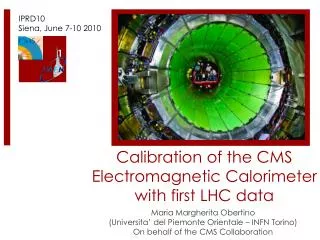
Pre-calibration In-situ calibration -symmetry w/jet trigger (ET > 120 GeV) Initial pre-calibration by ‘dead reckoning’ based on lab measurements (~4%) • Precision with 11M events • Limit on precision Inter-calibration precision % Lab LY Fast in-situ calibration based on principle that mean energy deposited by jet triggers is independent of at fixed (after correction for Tracker material)(~2-3% in few hours) 0 0.5 1.0 Test Beam LY = 4.0% -ringinter-calibration andZe+e cross-calibration (~1% in 1 day) Z e + e Barrel Test Beam LY – Lab LY Calibration strategy Lab measurements Reference pre-calibration of few SM with 50/120GeV electrons in test beam (<2%) Finally: calibration to < 0.5% with W + e in ~2 months 70 80 90 100 GeV Split 08/09/04 R M Brown - RAL 23
BarrelConstructionSchedule(1) End July 05 Cooling & Electronics Integration 2.7 SM/month RFI with4months margin Split 08/09/04 R M Brown - RAL 24
BarrelConstructionSchedule(2) Beg. Oct 2006 Split 08/09/04 R M Brown - RAL 25
EE Construction Schedule Mid. February 2008 Split 08/09/04 R M Brown - RAL 26
ECAL Barrel installation ECAL Endcap installation Installation Schedule May 2005: Delivery of installation tooling September 2005: Installation of 1 or 2 Supermodules for surface magnet test January 2006: EB+/- installation on surface May - October 2006: EB- Installation in cavern April 06 - Feb 2007: Cabling and commissioning of EB+ and EB- Dec 07 - Feb 2008: EE+/ES+ Installation and commissioning Feb - March 2008: EE-/ES- Installation and commissioning Split 08/09/04 R M Brown - RAL 27
Summary • High resolution electromagnetic calorimetry is a central design feature of CMS • The construction of the Barrel ECAL is proceeding well • Procurement of all major components is in hand for the Endcap ECAL • Crystal delivery is limiting the schedule for both Barrel and Endcap • Good progress is being made with actions to address this • The change in readout architecture has been an outstanding success • The Pre-shower detector is on course for completion as planned • A calibration strategy has been developed that avoids the requirement of measuring every Supermodule/Dee in an electron beam • Test beam results confirm the ECAL should meet its ambitious design goals Split 08/09/04 R M Brown - RAL 28