Download
1 / 14
140 likes | 231 Vues
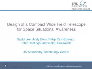
Integration of a Small Telescope System for Space Situational Awareness. Darcy Bibb Oceanit Mentor: Tony Bartnicki Advisor: Curt Leonard Home Institution: Maui Community College. Overview. Oceanit’s HANDS Satellites What’s out there? Why track them? System integration

E N D
Integration of a Small Telescope System for Space Situational Awareness Darcy Bibb Oceanit Mentor: Tony Bartnicki Advisor: Curt Leonard Home Institution: Maui Community College
Overview • Oceanit’s HANDS • Satellites • What’s out there? • Why track them? • System integration • Component assembly and configuration • System modeling and calibration • Polar alignment • Mount model • Autonomous tracking • System’s future
HANDS(High Accuracy Network Determination System) • Global network of low-cost, ground-based telescope systems • Capable of autonomously tracking satellites • Can provide accurate position data (metrics) of satellites • All systems are remotely accessible
Why track satellites? With over 8,000 man-made objects in orbit around Earth, the need to track these objects is apparent An optical system can: • Track own country’s assets in space • Keep track of where other countries’ satellites are situated • Determine possible collisions • Determine when and where objects will re-enter Earth’s atmosphere • Detect new objects in space
System Integration • Assembly of components into three basic assemblies: • Computer system • Weather sensors • Optical assembly • Combined assemblies make up overall complete telescope system
Computer System • Computer system integration • Install and wire individual components into portable server rack • Install and configure software on each server Front Back
Weather Sensors • Weather system integration • Mount and wire all weather sensors on a portable weather pole
Optical Assembly • Optical assembly integration • Install robotic telescope mount onto portable pier • Mount and balance optical tube assembly onto telescope mount • Mount and wire onto back of optical tube assembly: • CCD Camera • Focuser • Filter wheel
System Modeling • Polar alignment • Polar alignment aligns the rotational axis of the telescope mount parallel to the rotational axis of the Earth • Ensures accuracy of telescope movement and pointing • TPoint model • Uses mapped stars for additional calculations and corrections to improve mount alignment and external errors
Further Adjustments • Bring images into focus • Adjustments to telescope primary mirror – broad adjustments • Mechanical focuser between telescope and camera – fine adjustments Optical system out of focus Faint stars still appear out of focus Completely focused image
Autonomous Tracking • Software on Linux server configured for scheduled tasking and to provide scripts to software on the Windows server • Software on Windows server executed scripts for telescope movement, object tracking, and image capture • System successfully started up autonomously and began tracking satellites and saving images Ballistic tracking Sidereal tracking
Future of the System • With system capable of autonomous operation: • System will be moved into a test dome and set up • Verify system will operate and run autonomously • Complete system will run continuously for 21 days to test stability and operation • Upon successful completion of stability testing: • System will be disassembled and packaged • Deployed to final destination, and reassembled and set up on site • System will run autonomously and return data to control center
Acknowledgements • Maui Community College • Mark Hoffman • Maui Economic Development Board • Leslie Wilkins • 2008 Maui Short Course • Dave Harrington • Ryan Montgomery • Isar Mostafanezhad • Mark Pitts • Sarah Sonnet • Oceanit • Tony Bartnicki • Curt Leonard • Everyone at Oceanit, Maui • Center for Adaptive Optics • Scott Seagroves • Lynne Raschke • Hilary O’Bryan • Akamai Workforce Initiative • Lisa Hunter • Lani LeBron The Akamai Internship Program is funded by the Center for Adaptive Optics through its National Science Foundation Science and Technology Center grant (#AST-987683) and by grants to the Akamai Workforce Initiative from the National Science Foundation and Air Force Office of Scientific Research (both administered by the NSF, #AST-0710699) and from the University of Hawaii.