Download
1 / 25
260 likes | 386 Vues
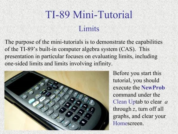
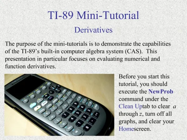
Assembly Programming on the TI-89. Created By: Adrian Anderson Trevor Swanson. TI-89 Calculator. Released in 1998 as a more portable version of the TI-92, which was much larger and had a QWERTY keyboard. Evaluates and performs algebraic expressions Performs calculus functions

E N D
Assembly Programming on the TI-89 Created By: Adrian Anderson Trevor Swanson
TI-89 Calculator • Released in 1998 as a more portable version of the TI-92, which was much larger and had a QWERTY keyboard. • Evaluates and performs algebraic expressions • Performs calculus functions • Can graph in several coordinate systems, including 3D • Has “pretty print”, meaning it draws algebraic expressions (such as radicals and exponents) in a mathematical way
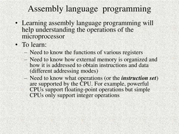
Assembly vs. TI-Basic • TI-Basic is simpler, but more restricted - Quick access to high-level features - Many ROM functions cannot be called from TI-Basic - Strict rules when calling other procedures - Must use the graph screen for pixel work in TI-Basic • Assembly is much faster • Assembly programs cannot be edited on the calculator
Motorola 68K Processor • Sixteen 32-bit registers and one 16-bit Condition Code Register (CCR) • The first 8 registers are data registers which can hold values associated with the assembly program • The next 8 are address registers which can serve as software stack pointers, index registers, or base address registers. The eighth of the address registers is the user stack pointer, a register which always holds the top value of the system stack • The final register, the 16-bit CCR, holds the conditions of the information from the most recent operation. These include carry, overflow, extend, zero, and negative.
Assembly Length Modifiers • Adding “.b” to the end of an instruction will make the instruction move data in bytes • Adding ".w" to the end of an instruction will cause the processor to treat the arguments as words. • Adding ".l" to the end of an instruction will treat the arguments as long words (32 bits). • Example: move.w #1,-(a7). Pushes the number 1 to the stack as a word.
Assembly Commands • Movement Instructions • move – Moves the data from one address to another • movem – Moves data from multiple locations to adjacent memory locations • clr – Clears the contents of a register. • lea – Loads an address to a register. • pea – Pushes data to the stack. • Arithmetic Instructions • add – Adds the source to the destination, and places it in destination. • addx – Like add, but adds 1 if the extend flag is set. • sub – Subtracts the source from the destination, and places the result in the destination • neg – Subtracts the data in the address from 0. • cmp – Subtracts the source from the destination, but does not store the result. Used to change the CCR. • muls.w – Multiplies the source by the destination, and places the result in the destination. • divs.w – Divides the destination by the source, and places the result in the destination.
Branch Instructions • bra – Sets the Program Counter (PC) ahead by a number of bytes equal to the argument. • b(cc) – Sets the PC forward by a number of bytes equal to the argument if a certain condition is set. • Condition Tests: • cs - True if the Carry bit is set • cc - True if the Carry bit is cleared • eq - "Equal to Zero" - True if the Zero bit is set • ne - "Not Equal to Zero" - True if the Zero bit is cleared • vs - True if the Overflow bit is set • vc - True if the Overflow bit is cleared • mi - "Minus" - True if the Negative bit is set • pl - "Plus" - True if the Negative bit is cleared • ge - "Greater than or Equal to Zero" - True if the Negative and Overflow are both cleared, or if they are both set. • lt - "Less than or Equal to Zero" - True if the Negative bit is set and the Overflow bit is cleared, or vice versa. • gt - "Greater than Zero" - As ge, but the Zero bit must also be cleared. • le - "Less than Zero" - As lt, but true if the Zero bit is set, regardless of the other conditions.
Rotate and Shift Instructions • asl – "Arithmetic Shift Left" - Moves the Most Significant Bit (MSB) into the Carry bit in the CCR, shifts each bit to the left, and inserts a 0 into the Least Significant Bit (LSB). • lsl – Works exactly as asl. • asr – Moves the LSB into the Carry bit in the CCR, shifts each bit to the right, and inserts a copy of the old MSB to the new MSB. • lsr – As asl, but places a zero in the MSB. • rol – Shifts each bit to the left, moves the MSB to the Carry flag in the CCR, and moves the Carry flag into the LSB. • roxl – As rol, but the Carry flag is then copied to the Extend bit. • ror – Shifts each bit to the right, moves the LSB to the Carry flag in the CCR, and moves the Carry flag into the MSB. • roxr – As ror, but the Carry flag is then copied to the Extend bit. • swap – Exchanges the high word in the specified register with the low word.
Binary Logic • not – Flips all bits in the destination • and – Performs a bitwise AND (destination bit is true only if both input bits are true) of the two values, and places the result in the destination • andi – As and, but the source is a constant • or – Performs a bitwise OR (destination bit is true if either source bit is true) of the two values, and places the result in the destination • ori – As or, but the source is a constant • eor – Performs a bitwise exclusive OR (destination bit is true of one source bit is true and one is false) of the two values, and places the result in the destination • eori – As eor, but the source is a constant
A Sample Program • Bounce.89z • A small ball continuously bounces off of the edges of the screen • Program flow: • Initialize variables and clear screen • Runs a loop to slow the program down • Check for keyboard press • Switch directions if ball hits a wall • Erase the ball • Moves the ball in the correct direction • Draws the ball
Advanced Techniques • Masking • A mask determines which bits will be set and which will not be set • Often uses and to erase unwanted bits • Jumptable • List of the locations of certain functions in memory • All functions can be called by addresses
Resources • Motorola 68k Family Programmer's Reference • http://www.freescale.com/files/archives/doc/ref_manual/M68000PRM.pdf • Techno-Plaza's TIGCC Assembly Lessons • http://www.technoplaza.net/assembly/ • Virtual TI Emulator • http://www.technoplaza.net/downloads/download.php?program=67 • Ticalc.org • http://www.ticalc.org/ • TI-89/TI-92 Plus Developer's Guide • http://education.ti.com/downloads/pdf/us/sdk8992pguide.pdf • The Official TIGCC Site • http://tigcc.ticalc.org/ • TI-89 Graphing Calculator Product Center • http://education.ti.com/us/product/tech/89/features/features.html