Download
1 / 31
320 likes | 327 Vues
Gulf Coast Community College EST 2606C Industrial Robotics LAB 7: Adept-One Robot I/O. OPTO-Isolator Before looking at the ADEPT I/O Schematics, let’s look at what an Opto-Isolator is and why it is necessary.

E N D
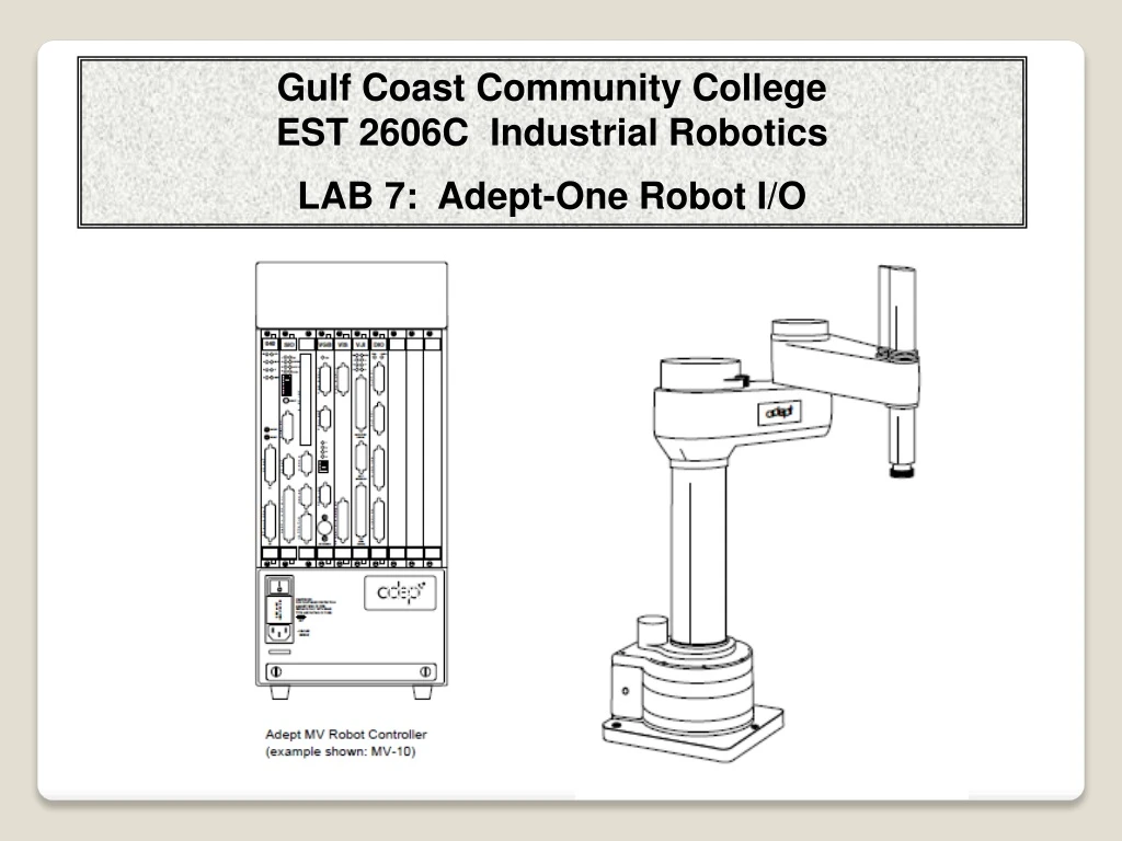
Gulf Coast Community College EST 2606C Industrial Robotics LAB 7: Adept-One Robot I/O
OPTO-Isolator Before looking at the ADEPT I/O Schematics, let’s look at what an Opto-Isolator is and why it is necessary. The opto-isolator is simply a package that contains both an infrared light-emitting diode (LED) and a photodetector such as a photosensitive transistor . The wave-length responses of the two devices are tailored to be as identical as possible to permit the highest measure of coupling possible. Other circuitry—for example an output amplifier—may be integrated into the package. An opto-isolator is usually thought of as a single integrated package, but opto-isolation can also be achieved by using separate devices.
OPTO-Isolator The device contains an LED and a phototransistor in a light-tight housing to exclude ambient light and without common electrical connection, positioned so that light from the LED will impinge on the photodetector. When an electrical signal is applied to the input of the opto-isolator, its LED lights and illuminates the photodetector, producing a corresponding electrical signal in the output circuit. Schematic diagram of a very simple opto-isolator with an LED and phototransistor. The dashed line represents the isolation barrier, over which there is no electrical contact.
OPTO-Isolator With a photodiode as the detector, the output current is proportional to the intensity of incident light supplied by the emitter. Unlike a transformer the opto-isolator allows DC coupling and can provide any desired degree of electrical isolation and protection from serious overvoltage conditions in one circuit affecting the other. . A simple circuit with an opto-isolator. When switch S1 is closed, LED D1 lights, which triggers phototransistor Q1, which pulls the output pin low. This circuit, thus, acts as a NOT gate.
OPTO-Isolator Applications: Optoisolation of microcontrollers is essential in cases where a microcontroller needs to supply signals to a controller which controls an inductive load such as a motor. Back EMF spikes from an inductive load can easily glitch, or destroy a microcontroller . Back EMF spikes typically manifest themselves as very short duration spikes which may or may not contain enough energy to actually destroy a microcontroller. Nevertheless, these spikes (which can easily approach 100V amplitudes) can easily glitch a microcontroller, even if transient suppression techniques such as generous use of decoupling capacitors, zener diodes etc. are used. Optocoupling should be thought of as absolutely essential if you are using microcontroller boards, and surface mounted boards!
OPTO-Isolator Applications: Among other applications, opto-isolators can help cut down on ground loops, block voltage spikes, and provide electrical isolation. Switched-mode power supplies use optocouplers for mains isolation. As they work in an environment with much electrical noise and with signals which are not small, optocouplers with low transmission ratio are preferred. Where electrical safety is paramount, optocouplers can totally isolate circuitry (which may be touched by humans) from mains electricity. Optocouplers are used to isolate low-current control or signal circuitry from transients generated or transmitted by power supply and high-current control circuits. The latter are used within motor and machine control function blocks.
Complete Adept-One System
AdeptOne-MV/Robot Controller Adept MV-19 Controller and PA-4 Power Chassis
Adept MV-19 Controller • The Adept MV-19 controller I/O • Has two cards with I/O • The SIO Card which has 20 digital • I/O: 12 inputs and 8 outputs • 2. Digital I/O Card has 64 I/O in groups or ports of 16 each with 32 inputs and 32 outputs. There are 4 groups with 16 bits each = 64
SIO Card (System Input/Output Module) The System Input/Output (SIO) module is a required module in all Adept MV controllers. The 2-slot-wide SIO is a 6U VME slave module that provides the system I/O functions for the controller. It serves as the system interface to mass storage (hard drive and floppy drive), E–Stop circuitry, three user RS-232 serial ports, 20 digital I/O channels, external front-panel control, and a real-time clock/calendar. Floppy Drive The 1.4 MB floppy drive can access both 720 KB and 1.44 MB floppy disks. Hard Drive The 256 MB internal hard drive is located inside the SIO module Serial I/O Connectors There are three RS-232 serial ports for general-purpose serial I/O functions. These global serial ports are referred to as devices SERIAL:1, SERIAL:2, and SERIAL:3. These serial ports can be accessed, via the VMEbus, by any Adept system processor configured to to run V+ External Front Panel (VFP-1) The optional external VME front panel (VFP) is connected to the FP/MCP connector on the SIO module.
Digital I/O Connector Pin Locations on SIO Module Adept MV Controller page 91
DIO Card (Digital Input/Output Module) The Adept Digital I/O module is an opto-isolated 64-channel digital I/O module with 32 input channels and 32 output channels.
Digital Input/Output Module (DIO) Inputs: The 32 input channels are arranged in four groups of eight. Each group is electrically opto-isolated from the other groups and from the VME bus circuitry. The eight inputs within each group share a common ground. The inputs are accessed through the two 26-pin D-sub Input connectors on the front of the module. Each connector provides access to two input groups. Each group requires 10 pins: 8 Input signals and 2 Ground references. An input is turned on by providing a positive potential on its input pin relative to the ground pin of its group. This type of input is considered “sinking”, that is, to turn it on, current must flow into the input pin.
Digital Input/Output Module (DIO) Outputs: The 32 output channels are arranged in four groups of eight. Each group is electrically opto-isolated from the other groups and from the VMEbus circuitry. The eight outputs within each group share a common power supply and a common ground. The outputs are accessed through the two 44-pin D-sub Output connectors on the front of the module. Each connector provides access to two output groups. Each group requires 19 pins: 8 output signals, 1 test signal, 9 power supply (all tied together), and 1 power supply ground reference. When an output is on, current will flow in through the power supply pins and out of the output pins. This type of output is considered “sourcing,” that is, in the on condition, current flows out of the output pin. Each output channel (circuit) should be connected to only one output device.
Digital Input/Output Module (DIO) – DIP Switches More than one card can be installed for additional I/O. Setting the dip switches changes the addresses on the second card. Switch and Jumper Locations on DIO PC Board
ADEPT-ONE Robot I/O Testing and Programming
Programming ADEPT I/O Digital I/O Adept controllers can communicate in a digital fashion with external devices using the Digital I/O capability. Digital input reads the status of a signal controlled by user-installed equipment. A typical digital input operation is to wait for a microswitch on a workcell conveyor to close, indicating that an assembly is in the proper place. The WAIT Instruction: The WAIT instruction and SIG function are used to halt program execution until a digital input channel signal achieves a specified state. The program line: WAIT SIG(1001) halts program execution until a switching device attached to digital input channel 1001 is closed
Programming ADEPT I/O SIGNAL Instruction: TheSIGNALinstruction is used for digital output. In the above example, the conveyor belt may need to be stopped after digital input signal 1001 signals that a part is in place. The instruction: SIGNAL(-33) turns off digital output signal 33, causing the conveyor belt connected to signal 33 to stop. When processing on the part is finished and the part needs to be moved out of the work area, the instruction: SIGNAL(33) turns the conveyor belt back on. The digital I/O channels must be installed before they can be accessed by the SIG function or SIGNAL instruction.
Programming ADEPT I/O IF THEN Instruction: If signal 1002 is a sensor indicating a part feeder is empty, the code: IF SIG(1002) THEN ;+ signal received CALL service.feeder() call subroutine program END Soft Signals: Soft signals are used primarily as global flags. The soft signals are in the range 2001 - 2512 and can be used with SIG and SIGNAL. A typical use of soft signals is for intertask communication. Soft signals may be used to communicate between different V+ systems running on multiple system processors.
Gulf Coast Community College EST 2606C Industrial Robotics LAB 7: Adept-One Robot I/O The Lab Assignments
Lab Assignments for Lab 7: Part 1 Study the wiring I/O wiring.packet of schematics for the four ADEPT-ONE Robots and fill out the address for your robot.
Lab Assignments for Lab 7: Part 1 Continued: Test the ADEPT-ONE outputs signals for the grippers.. .DO SIGNAL 3001 Close small gripper. .DO SIGNAL - 3001 Open small gripper. .DO SIGNAL 3002 Close large gripper. .DO SIGNAL - 3002 Open Large Gripper .DO SIGNAL 3003 Flip the grippers .DO SIGNAL - 3003 Flip the grippers back.
Lab Assignments for Lab 7: Part 1 Continued: 3. Using the Monitor, Test the I/O (see the chart you filled out in step 1). In the ADEPT-ONE monitor, type IO on the screen to display the Input signals that are active. Control C lets you exit the program. Block the photo sensor and identify the position for input 1037. What is the status ( 1 or 0) of the input? 4. Test the remaining inputs up to 1040 by placing a temporary jumper from +24vdc at the end of the terminal blocks to the appropriate input terminal in the I/O box. A “1” or a “0” will show on the screen. CAUTION: do not touch the ground with the wire connected to +24vdc to the opposite end of the terminal block for this test. 5. Activate the following PLC outputs one at a time to test the Adept inputs. What are the addresses for the PLC switch for your robot. 6.. Activate the following Adept outputs to the PLC inputs one at a time to test the communication signals. What are the addresses for the PLC inputs for your robot? (See handout of schematics)
Lab Assignments for Lab 7: • Part 2 – Develop a program to test Signals. • Develop a program that sends signals and receive signals from the PLC when the photocell is activated. • Wait for the photo sensor to be activated (break the beam). It is wired to be active low. So check for a low at Adept signal input 1037. When the beam is broke the program continues. • The ADEPT robot will signal 0033 to the PLC input 0 (PLC Address ___________) You should see a light come on the PLC control panel. • Using the override switches on the PLC, send back a signal to the ADEPT input 1033. then your Adept program prints on the screen. “Signal A has been received” • Prompt for the operator to press a key on the keyboard to continue. Type that instruction on • screen. • 5. The ADEPT robot will signal 0034 to the PLC input 1 (PLC Address ___________) • The PLC Host sends a signal back to the ADEPT input 1034 then prints on the screen. • “Signal B has been received” • Communication should now be operational. Two signals sent to the PLC from the robot and two signals received from the PLC from to the Robot. In addition, the photo sensor should now be operational.
Have Fun, but be careful The End