Download
1 / 35
350 likes | 357 Vues
Electron cloud and ion effects in SuperKEKB. H. Fukuma, KEK. SuperB2008. 2008.05.31, Elba, Italy. I. Introduction. II. Electron cloud effects. III. Ion effects. IV. Summary. I. Introduction. • SuperKEKB is an upgrade plan of KEKB. LER / HER. Parameters. 5 - 10 10 35 cm -2 sec -1.

E N D
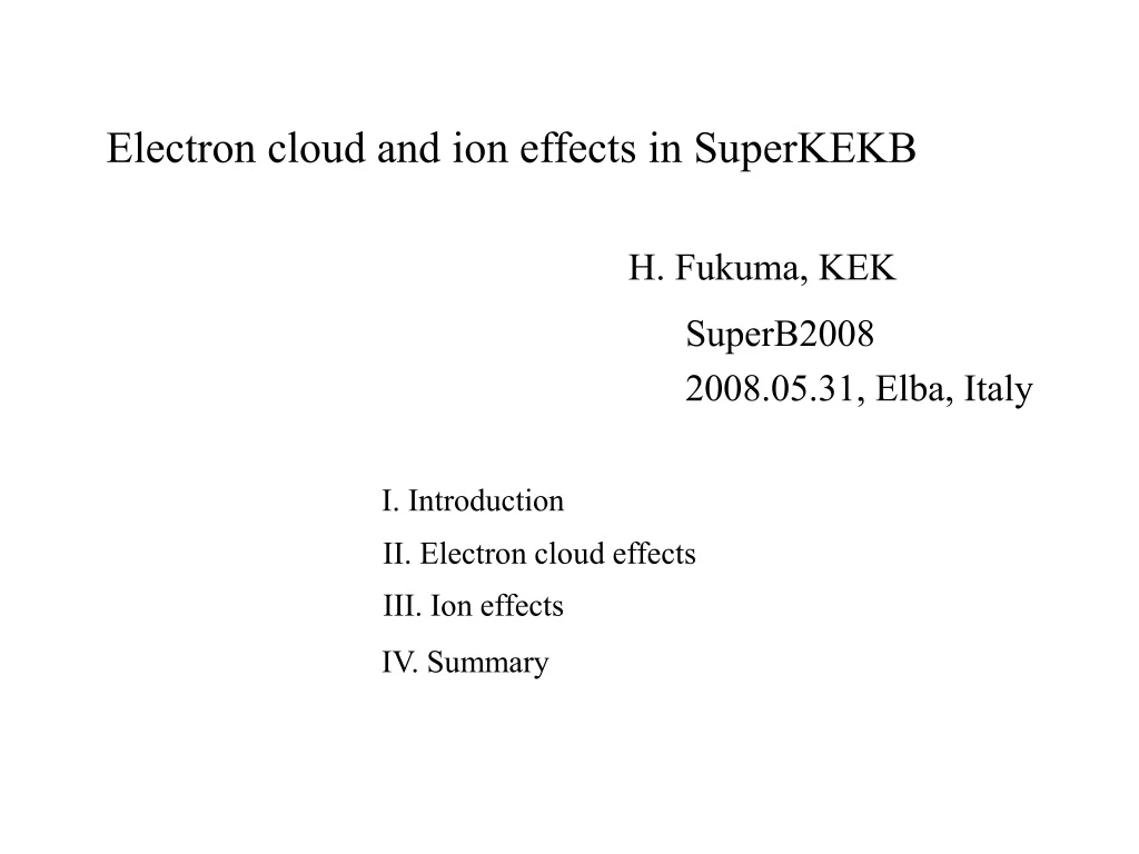
Electron cloud and ion effects in SuperKEKB H. Fukuma, KEK SuperB2008 2008.05.31, Elba, Italy I. Introduction II. Electron cloud effects III. Ion effects IV. Summary
I. Introduction •SuperKEKB is an upgrade plan of KEKB. LER / HER Parameters 5 - 10 1035 cm-2 sec-1 Luminosity Beam energy 3.5 / 8.0 GeV Beam current 9.4 / 4.1 A Number of bunches 5018 Circumference 3016 m 0.6 m Bunch spacing 24 nm Emittance •In SuperKEKB, the electron/positron beam may be stored in LER/HER after LINAC upgrade in order to mitigate the electron cloud effects ("charge switch"). •The ion effects would be stronger and the electron cloud effects be weaker than those before the charge switch. •So far two effects were studied mainly assuming the charge switch. •This talk also assumes it.
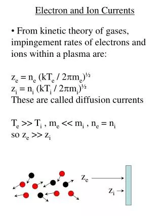
II. Electron cloud effects •Photoelectrons produced by synchrotron radiation and secondary electrons produced by impinging electrons on a chamber wall form an electron cloud in positron storage rings. •The interaction between the electron cloud and a beam leads to the electron cloud effects such as single- and multi-bunch instability, the tune shift, the increase of pressure and so on. •Above all a beam blowup caused by the strong head-tail instability is one of the issues in KEKB though it is largely mitigated by solenoid winding in field free regions. • In SuperKEKB, TiN coated ante-chambers and solenoids will be installed to reduce the number of electrons.
1. Buildup of electron cloud •Cloud buildup was calculated by 3D PIC code “CLOUDLAND” developed by L.F. Wang. •Assumption a) Round chamber b) Uniform production of primary electrons on chamber wall. c) Effect of ante-chamber Primary electron yield of 0.01 is artificially used in order to take into account of the reduction of electron yield by the ante-chamber.
•Parameters used in a simulation of electron cloud buildup Beam energy(GeV) 8 Bunch spacing(ns) 2 Number of particles in a bunch 5.2 1010 Chamber radius(mm) 37 Maximum secondary emission yield 1.5 Energy of maximum secondary yield 250eV Number of bunches 200 Number of train 1 Primary electron yield 0.01 rms bunch length(mm) 3 Horizontal emittance(m) 2.4 10-8 Vertical emittance(m) 4.8 10-10 Average horizontal beta function (m) 10 Average vertical beta function (m) 10
•Distribution of electron cloud a) Drift space without solenoid Central density of electrons is very high. H. Fukuma and L. Wang, PAC2005.
b) Quadrupole magnet No saturation Trapping At the end of bunch train Trapped electrons At a bunch gap (40ns after the last bunch in the train) Trapping of electrons is seen.
c) Dipole magnet Two stripes of electrons appear.
d) Uniform solenoid field of 60G Trapping 60 G is enough to suppress the electron cloud near the beam.
•Average electron volume density and electron volume density at a pipe center in various magnetic fields Field strength average (1012m-3) at pipe center (1012m-3) Drift space - 1.0 10 Dipole 0.25(T) 20.0 0.6 Quadrupole 10.3(T/m) 8.4 0.46 Solenoid 60(G) 0.61 0.0 Solenoid field of 60G is very effective. Electron cloud remains inside bending and quadrupole magnets. Integrated electron density along the ring = 0.6 x 10¹⁵m-2
2. Strong head-tail instability •According to the theory K. Ohmi and F. Zimmermann, instability occurs if r:density of electrons, s:orbit length by:beta function, ns:synchrotron tune 0.6 x 10¹⁵m-2 4.5 x 10¹⁵m-2 (from simulation) •Left side is smaller than right side, which indicates the electron density is below threshold of the instability. 3. Tune shift •A betatron tune shift by the electric field of the electron cloud is = 0.0005
4. Coupled bunch instability •Coupled bunch instability(CBI) by the electron cloud was studied by PEI code developed by K. Ohmi. •Comparison between positron storage in LER and HER was done. S. S. Win et al., APAC2004.
a) Cloud buildup without solenoid with 60G solenoid • Electron density is almost same in HER and LER.
b) Bunch oscillation by CBI by a tracking Damping time of bunch-by-bunch FB system at KEKB is 0.2 ms (20 turns). •Growth rate in LER is larger than that in HER. •Large growth rate might be caused by a trapping of electrons in solenoid. Needs further study.
5. Summary of electron cloud effects • Electron cloud effects are estimated in the positron storage in HER. a) Solenoid field of 60G is very effective to reduce the electron density around the center of a chamber. b) Simulated electron density is below the threshold of the strong head-tail instability. c) Substantial electron cloud stays inside bending and quadrupole magnets. d) Growth rate of the coupled bunch instability should be studied more. • Remaining works are, a) Refinement of input parameters for simulations i) final design of a size and shape of the chamber ii) secondary emission coefficient etc. b) Positron storage in LER
III. Ion effects •After the charge switch, 3.5 GeV ◊Beam energy : 8 9.4A ◊Beam current :4.1 •Larger vacuum pressure than KEKB : 5 nTorr (CO) Ion instability would be strong enough to degrade the luminosity. •Requirements from operation ◊Residual centroid oscillation by the instability should be small. ◊Tune shift along the train by the ions should be small. ◊Number of bunches should be maximized if train gaps are introduced to mitigate the ion effects. Small number of train gaps is desirable.
1. Ion trapping •Ions are trapped for a long time in a beam potential. •A bunch interacts with an ion again and again in many turns. •Ion motion p bunches y : ion coordinate n : turn of a bunch train c ion h-p gaps kick by a bunch Nb : number of electrons / bunch, m, Mion : electron and ion mass, x,y : beam size of electron bunch •Stability condition
•Trace |M|/2 in SuperKEKB is the same order of magnitude as that in KEKB. •According to the linear theory, ion trapping would be avoided with a train gap of 2 % RF buckets in SuperKEKB.
bunch ion 2. Fast ion instability (FII) •The ions created by the head of the bunch train affect to the tail. •The FII is a single pass coupled-bunch instability (possibly seen at a ring but also a linac or a beam transport line). •The instability is transient. ◊If damping such as radiation damping exists, the oscillation is damped from the head to the tail in the train then the oscillation of all bunches is finally damped (A. W. Chao and G. V. Stupakov). ◊Actually an equilibrium amplitude is determined by the balance of the excitation of the instability by the noises and the damping.
1) Linear theory (G. V. Stupakov et al., P.R.E. 52, 5499) z •The offset of the centroid of the beam y(s,z) is given by s . 0 (ion frequency) , : ion line density / bunch , ngas: gas density b: bunch population , : Atomic mass number of ions , sb: bunch spacing •Assuming a solution of , Q : quality factor of ion oscillations
•Behavior of the amplitude growth ◊Linear regime without decoherence of the ions log (amplitude) nonlinear regime (linear growth) ◊Linear regime with decoherence of the ions 1 y ◊Nonlinear regime (S. Heifets) linear regime (exponential growth) turns
•Numerical example in SuperKEKB (a long train) Energy 3.5 GeV Bunch spacing : 2ns (=0.6m) Number of bunch : 5120 Bunch current : 1.9 mA Pressure : 1 nTorr (CO) Emittance (H/V) : 24 nm/0.96 nm Beam size (H/V) : 0.6 mm/0.12 mm Beta function (H/V) : 15 m/15 m Tune(V) : 43.545 Q : 10 less than one turn (revolution time : 10 s)
2) Mitigation method A) Decrease the ion density a) Better vacuum pressure •This might be an ultimate cure, but may be difficult. + electrode b) Clearing electrode 2a rc •A condition where an ion is not trapped in a potential well by a dc beam, ion (A. Poncet) - for SuperKEKB. It looks very high. •Introducing gaps makes motion of ions unstable. •Ions might be collected on electrodes with smaller voltage. A simulation is necessary for studying the effectiveness of the electrodes.
c) Gaps in a bunch train (J. Seeman) nb : the number of bunches •Growth rate •If a train is divided by ten gaps 0.01 =10 turns 1000 turns •Very effective, but loose luminosity because the number of bunches decreases due to the gaps. d) Beam shaking (9th KEKB Accelerator Review Committee(ARC)) •Shaking the beam may resonantly excite the ion motion, then ions will be lost. •Most effective shaking frequency i (ion tune) +/- fractional betatron tune )0 ≈ 24MHz •Amplitude of the excitation should be small so as not to loose the luminosity. Experiment or simulation will be interesting.
B) Damp the bunch oscillation a) Transverse bunch-by-bunch feedback system •A damping time of the bunch-by-bunch feedback in KEKB is 20 turns. •It could not suppress the beam oscillation in rapid growth region if full buckets are occupied. kicker •Possibility to increase gain limit by multiple feed back systems (9th KEKB ARC) signal •4 systems with feedback delays of a quarter of a turn pick up 4 times faster damping time •Straight signal paths cutting across the arcs must be provided to match the beam flight time. •A feasibility study is necessary.
b) Tune spread among bunches •It is well known that tune spread among bunches stabilize the coupled bunch instability. Tune spread , if tg is 10 turns. : growth time of a mode •According to the experience of KEKB, stable operation will be impossible. c) Octupoles •Non-linear, amplitude depended tune shift by octupoles will damp the coherent oscillation of a bunch due to filamentation in a phase space. too strong.
d) Lower vertical emittance or beam size (K. Oide) •Amplitude saturates at about y. •A reduction of the vertical emittance by a factor 2 will give a design beam size. 0.5% coupling. (KEKB 5% @collision) e) Beam-beam detuning (Actually this is not a cure, but a mitigation effect.) (A. Chao, "NONLINEAR BEAM-BEAM RESONANCES", AIP Proceedings No. ?) y/x=0.012 0.93 beam-beam parameter x=0 y/y d=67 turns tune shift @1y =0.015 for =0.0036 for
Hereafter we discuss thegaps in a bunch train for mitigation method because it seems simplest way among above mentioned methods. 3) Estimation of growth time •Conditions to be taken into account a) Train gap should be less than 200 ns to avoid the effect of the transient beam loading on the RF system (K. Akai). b) The vacuum pressure is 5 nTorr for CO and 10 nTorr for H2 to get a lifetime of 10 hr (Y. Suetsugu). c) Typical damping time of the bunch-by-bunch feedback system is 0.2 ms from the experience of KEKB.
•A code developed by L. F. Wang was used in simulations. ◊Features 1) 2D space charge 2) Tracking through elements 3) Realistic vacuum model (various pressure and multi-gas species) 4) Any beam fill pattern 5) Bunch-by-bunch feedback 6) Wake of ion-cloud …
A) Growth time from the tracking 50 trains; train Gap=20 buckets Number of bunch per train=82 Total number of bunch=50*82= 4100 Pressure=1nTorr Growth time=35turns=0.35 ms H. Fukuma and L. Wang, ECLOUD07.
B) Growth rate from the ion density number of train =50 number of bunch per train=82 gap=40ns (20 missing bunch) •Estimated growth rate emittancex=2.4E-8, emittancey=4.8E-10 pressure : 0.75 nTorr •This relation in our calculation is valid even if the gap is changed. •We estimated the growth rate@1nTorr from the ion density @0.75 Torr .
gap 15 gap 10 gap 20 Train length vs. estimated growth rate •From the growth rate and the damping rate of the feedback system the storable total number of bunches is determined, then we can get the relation between the luminosity loss and the growth rate. •If the pressure of CO is 5 nTorr and the growth rate should be less than 5 ms-1, which is the damping rate of the feedback, the bunches in a train should be less than 35, which leads to the luminosity loss of about 40%. damping rate of the feedback •If the pressure of CO is 1 nTorr and the growth rate should be less than 5 ms-1, 150 bunches in a train would be possible, which leads to the luminosity loss of about 15%.
4) Tune shift •Beam-ion force changes the tune of the bunches. •As the ion density changes along the train, the tune also changes along the train. 50 trains; train Gap=20 Number of bunch per train=82 Total number of bunch=50*82= 4100 P=1nTorr Growth time=35turns; tune shift=0.0035 •The vertical tune shift of the last bunch in the train was estimated using the ion density from the simulation as,
5 nTorr (gap 20) 1 nTorr (gap 15) 1 nTorr (gap 10) 1 nTorr (gap 20) Tune shift of the last bunch •In KEKB, ◊Tune change of 0.001 affects to the luminosity. ◊Vertical tune in LER changes 0.0018 along the train due to the electron cloud. Tune change of 0.002 along the train would be a good reference which is acceptable in SuperKEKB. •From the pressure and the allowable tune shift the storable total number of bunches is determined, then we can get the relation between the luminosity loss and the pressure. •If the pressure of CO is 5 nTorr and the tune shift along the train should be less than 0.002, the bunches in the train should be less than 25, which leads to the luminosity loss of 45 %. •If the pressure of CO is 1 nTorr, 135 bunches in a train would be possible, which leads to the luminosity loss of 15 %.
3. Summary of ion effects •The train length to mitigate the FII and the tune shift was discussed when electrons are stored in LER at SuperKEKB. •When the pressure of CO is 5 nTorr, assuming the damping rate of the feedback system of 5 ms-1, length of the train would be limited to 35, which leads to the luminosity loss of about 40%. if the tune shift due to the ions should be less than 0.002, length of the train would be limited to 25, which leads to the luminosity loss of about 45%. •If the pressure of CO is 1 nTorr, the luminosity loss due to the growth rate and the tune shift will be 15 % and 15 %, respectively. •The CO pressure of 1 nTorr will be necessary for SuperKEKB if electrons are stored in LER. •The tune shift would be as much serious as the amplitude growth by the FII.