Download
1 / 57
570 likes | 666 Vues
Chapter 12: Mass-Storage Systems. Spring 2012. Chapter 12: Mass-Storage Systems. Overview of Mass Storage Structure Disk Structure Disk Attachment Disk Scheduling Disk Management Swap-Space Management RAID Structure Disk Attachment Stable-Storage Implementation

E N D
Chapter 12: Mass-Storage Systems Spring 2012
Chapter 12: Mass-Storage Systems • Overview of Mass Storage Structure • Disk Structure • Disk Attachment • Disk Scheduling • Disk Management • Swap-Space Management • RAID Structure • Disk Attachment • Stable-Storage Implementation • Tertiary Storage Devices • Operating System Issues • Performance Issues
Objectives • Describe the physical structure of secondary and tertiary storage devices and the resulting effects on the uses of the devices • Explain the performance characteristics of mass-storage devices • Discuss operating-system services provided for mass storage, including RAID and HSM
Overview of Mass Storage Structure • Magnetic disks provide bulk of secondary storage of modern computers • Drives rotate at 60 to 200 times per second • Transfer rate is rate at which data flow between drive and computer • Positioning time (random-access time) is time to move disk arm to desired cylinder (seek time) and time for desired sector to rotate under the disk head (rotational latency) • Head crash results from disk head making contact with the disk surface • That’s bad • Disks can be removable • Drive attached to computer via I/O bus • Busses vary, including EIDE, ATA, SATA, USB, Fibre Channel, SCSI • Host controller in computer uses bus to talk to disk controller built into drive or storage array
Overview of Mass Storage StructureMagnetic Disks… • Disks can be removable • Drive attached to computer via I/O bus • Busses vary, including • Enhanced Integrated Drive Electronics (EIDE) • Advanced Technology Attachment (ATA) • Serial ATA (SATA) • Universal Serial Bus (USB) • Fiber Channel (FC) • Small Computer System Interface (SCSI) • Host controller in computer uses bus to talk to disk controller built into drive or storage array
Moving-head Disk Mechanism • Thousands of concentric cylinders • Each track has hundreds of sectors • Can read-write on both sides of the platter
Overview of Mass Storage Structure (Cont.) • Magnetic tape • Was early secondary-storage medium • Relatively permanent and holds large quantities of data • Access time slow • Random access ~1000 times slower than disk • Mainly used for backup, storage of infrequently-used data, transfer medium between systems • Kept in spool and wound or rewound past read-write head • Once data under head, transfer rates comparable to disk • 20-200GB typical storage • Common technologies are 4mm, 8mm, 19mm, LTO-2 and SDLT
Disk Structure • Disk drives are addressed as large 1-dimensional arrays of logical blocks, where the logical block is the smallest unit of transfer. • The 1-dimensional array of logical blocks is mapped into the sectors of the disk sequentially. • Sector 0 is the first sector of the first track on the outermost cylinder. • Mapping proceeds in order through that track, then the rest of the tracks in that cylinder, and then through the rest of the cylinders from outermost to innermost.
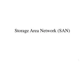
Disk Attachment • Host-attached storage accessed through I/O ports talking to I/O busses • SCSI itself is a bus, up to 16 devices on one cable, SCSI initiator requests operation and SCSI targets perform tasks • Each target can have up to 8 logical units (disks attached to device controller • FC is high-speed serial architecture • Can be switched fabric with 24-bit address space – the basis of storage area networks (SANs) in which many hosts attach to many storage units • Can be arbitrated loop (FC-AL) of 126 devices
Network-Attached Storage • Network-attached storage (NAS) is storage made available over a network rather than over a local connection (such as a bus) • NFS and CIFS are common protocols • Implemented via remote procedure calls (RPCs) between host and storage • New iSCSI protocol uses IP network to carry the SCSI protocol
Storage Area Network • Common in large storage environments (and becoming more common) • Multiple hosts attached to multiple storage arrays - flexible
Disk Scheduling • The operating system is responsible for using hardware efficiently — for the disk drives, this means having a fast access time and disk bandwidth. • Access time has two major components • Seek time is the time required for the disk to move the heads to the cylinder containing the desired sector. • Rotational latency is the additional time waiting for the disk to rotate the desired sector to the disk head. • Minimize seek time • Seek time seek distance • Disk bandwidth is the total number of bytes transferred, divided by the total time between the first request for service and the completion of the last transfer.
Disk Scheduling (Cont.) • Several algorithms exist to schedule the servicing of disk I/O requests. • We illustrate them with a request queue (0-199). 98, 183, 37, 122, 14, 124, 65, 67 Head pointer 53
FCFS Illustration shows total head movement of 640 cylinders. 45 85 146 85 108 110 59 2 640
SSTF • Shortest Seek Time First • Selects the request with the minimum seek time from the current head position. • SSTF scheduling is a form of SJF scheduling; may cause starvation of some requests. • Illustration shows total head movement of 236 cylinders.
SCAN • The disk arm starts at one end of the disk, and moves toward the other end, servicing requests until it gets to the other end of the disk, where the head movement is reversed and servicing continues. • Sometimes called the elevator algorithm. • Illustration shows total head movement of 208 cylinders.
C-SCAN • Provides a more uniform wait time than SCAN. • The head moves from one end of the disk to the other. servicing requests as it goes. When it reaches the other end, however, it immediately returns to the beginning of the disk, without servicing any requests on the return trip. • Treats the cylinders as a circular list that wraps around from the last cylinder to the first one.
C-SCAN (Cont.) 382 cylinder movements
C-LOOK • Version of C-SCAN • Arm only goes as far as the last request in each direction, then reverses direction immediately, without first going all the way to the end of the disk.
C-LOOK (Cont.) 322 cylinder movements
Selecting a Disk-Scheduling Algorithm • SSTF is common and has a natural appeal • SCAN and C-SCAN perform better for systems that place a heavy load on the disk. • Performance depends on the number and types of requests. • Requests for disk service can be influenced by the file-allocation method. • The disk-scheduling algorithm should be written as a separate module of the operating system, allowing it to be replaced with a different algorithm if necessary. • Either SSTF or LOOK is a reasonable choice for the default algorithm.
Disk Management • Low-level formatting, or physical formatting — Dividing a disk into sectors that the disk controller can read and write. • To use a disk to hold files, the operating system still needs to record its own data structures on the disk. • Partition the disk into one or more groups of cylinders. • Logical formatting or “making a file system”. • Boot block initializes system. • The bootstrap is stored in ROM. • Bootstrap loader program. • Methods such as sector sparing used to handle bad blocks. • Set aside sectors to use in case other sectors go bad.
Disk Formatting (1) A disk sector
Disk Formatting (2) An illustration of cylinder skew
Disk Formatting (3) (b) Single interleaving (a) No interleaving (c) Double interleaving
Error Handling (a) A disk track with a bad sector (b) Substituting a spare for the bad sector (c) Shifting all the sectors to bypass the bad one
Booting from a Disk in Windows 2000 MBR: Master Boot Record
Swap-Space Management • Swap-space — Virtual memory uses disk space as an extension of main memory. • Swap-space can be carved out of the normal file system,or, more commonly, it can be in a separate disk partition. • Swap-space management • Version 4.3BSD UNIX allocates swap space when process starts; holds text segment (the program) and data segment. • Kernel uses swap maps to track swap-space use. • Solaris 2 allocates swap space only when a page is forced out of physical memory, not when the virtual memory page is first created.
Data Structures for Swapping on Linux Systems Swap Space consists of 4KB page slots Swap map tracks the swap pages. >0 indicates the page is occupied Number >1 indicates number of processes using that swapped page
RAID Structure • RAID (Redundant Array of Independent Disks) – multiple disk drives provides reliability via redundancy. • Increases the mean time to failure • Frequently combined with NVRAM to improve write performance • RAID is arranged into six different levels.
RAID (Cont) Several improvements in disk-use techniques involve the use of multiple disks working cooperatively Disk striping uses a group of disks as one storage unit RAID schemes improve performance and improve the reliability of the storage system by storing redundant data Mirroring or shadowing (RAID 1)keeps duplicate of each disk Striped mirrors (RAID 1+0) or mirrored stripes (RAID 0+1) provides high performance and high reliability Block interleaved parity (RAID 4, 5, 6)uses much less redundancy RAID within a storage array can still fail if the array fails, so automatic replication of the data between arrays is common Frequently, a small number of hot-spare disks are left unallocated, automatically replacing a failed disk and having data rebuilt onto them
Striping • Bit level striping • Store bits across the disk system • If have 8 disks, write bit i of each byte to disk i. • Every disk participates in every access (read/write) • Block level striping • Blocks of a file are striped across multiple disks
RAID Levels • Level 0 • Striping at block level without redundancy • Level 1 • Disk mirroring • Level 2 • Use parity bits to detect and correct errors • Single parity bit detect one error • Two parity bits detect two errors and correct one • Level 3 • Bit interleaved parity • Uses single disk to store parity bit • Parity disk bottleneck because each read/write must access that disk
RAID Levels… • Level 4 • Same as level 3 except does block interleaved parity • Level 5 • Striped set with distributed parity • Requires all but one drive to be present to operate • Drive failure requires replacing the failed drive • Level 6 • Striped set with dual distributed parity • Provides fault tolerance from two drive failures
RAID (0 + 1) and (1 + 0) • 0 + 1 • Combines Raid 0 and Raid 1 • Raid 0 provides performance, Raid 1 provides reliability • Need double the disk drives • 1 + 0 • Disks are mirrored in pairs, and resulting mirrored pairs are striped • Failure in one disk only leaves that disk unavailable, but it’s mirrored pair is still available
Stable-Storage Implementation • Write-ahead log scheme requires stable storage. • To implement stable storage: • Replicate information on more than one nonvolatile storage media with independent failure modes. • Update information in a controlled manner to ensure that we can recover the stable data after any failure during data transfer or recovery.
Tertiary Storage Devices • Low cost is the defining characteristic of tertiary storage. • Generally, tertiary storage is built using removable media • Common examples of removable media are floppy disks and CD-ROMs; other types are available.
Removable Disks • Floppy disk — thin flexible disk coated with magnetic material, enclosed in a protective plastic case. • Most floppies hold about 1 MB; similar technology is used for removable disks that hold more than 1 GB. • Removable magnetic disks can be nearly as fast as hard disks, but they are at a greater risk of damage from exposure.
Removable Disks (Cont.) • A magneto-optic disk records data on a rigid platter coated with magnetic material. • Laser heat is used to amplify a large, weak magnetic field to record a bit. • Laser light is also used to read data (Kerr effect). • The magneto-optic head flies much farther from the disk surface than a magnetic disk head, and the magnetic material is covered with a protective layer of plastic or glass; resistant to head crashes. • Optical disks do not use magnetism; they employ special materials that are altered by laser light.
WORM Disks • The data on read-write disks can be modified over and over. • WORM (“Write Once, Read Many Times”) disks can be written only once. • Thin aluminum film sandwiched between two glass or plastic platters. • To write a bit, the drive uses a laser light to burn a small hole through the aluminum; information can be destroyed by not altered. • Very durable and reliable. • Read Only disks, such ad CD-ROM and DVD, com from the factory with the data pre-recorded.
Tapes • Compared to a disk, a tape is less expensive and holds more data, but random access is much slower. • Tape is an economical medium for purposes that do not require fast random access, e.g., backup copies of disk data, holding huge volumes of data. • Large tape installations typically use robotic tape changers that move tapes between tape drives and storage slots in a tape library. • stacker – library that holds a few tapes • silo – library that holds thousands of tapes • A disk-resident file can be archived to tape for low cost storage; the computer can stage it back into disk storage for active use.
Operating System Issues • Major OS jobs are to manage physical devices and to present a virtual machine abstraction to applications • For hard disks, the OS provides two abstraction: • Raw device – an array of data blocks. • File system – the OS queues and schedules the interleaved requests from several applications.
Application Interface • Most OSs handle removable disks almost exactly like fixed disks — a new cartridge is formatted and an empty file system is generated on the disk. • Tapes are presented as a raw storage medium, i.e., and application does not not open a file on the tape, it opens the whole tape drive as a raw device. • Usually the tape drive is reserved for the exclusive use of that application. • Since the OS does not provide file system services, the application must decide how to use the array of blocks. • Since every application makes up its own rules for how to organize a tape, a tape full of data can generally only be used by the program that created it.
Tape Drives • The basic operations for a tape drive differ from those of a disk drive. • locate positions the tape to a specific logical block, not an entire track (corresponds to seek). • The read position operation returns the logical block number where the tape head is. • The space operation enables relative motion. • Tape drives are “append-only” devices; updating a block in the middle of the tape also effectively erases everything beyond that block. • An EOT mark is placed after a block that is written.
File Naming • The issue of naming files on removable media is especially difficult when we want to write data on a removable cartridge on one computer, and then use the cartridge in another computer. • Contemporary OSs generally leave the name space problem unsolved for removable media, and depend on applications and users to figure out how to access and interpret the data. • Some kinds of removable media (e.g., CDs) are so well standardized that all computers use them the same way.
Hierarchical Storage Management (HSM) • A hierarchical storage system extends the storage hierarchy beyond primary memory and secondary storage to incorporate tertiary storage — usually implemented as a jukebox of tapes or removable disks. • Usually incorporate tertiary storage by extending the file system. • Small and frequently used files remain on disk. • Large, old, inactive files are archived to the jukebox. • HSM is usually found in supercomputing centers and other large installations that have enormous volumes of data.
Speed • Two aspects of speed in tertiary storage are bandwidth and latency. • Bandwidth is measured in bytes per second. • Sustained bandwidth – average data rate during a large transfer; # of bytes/transfer time.Data rate when the data stream is actually flowing. • Effective bandwidth – average over the entire I/O time, including seek or locate, and cartridge switching.Drive’s overall data rate.