Download
1 / 39
800 likes | 2.25k Vues
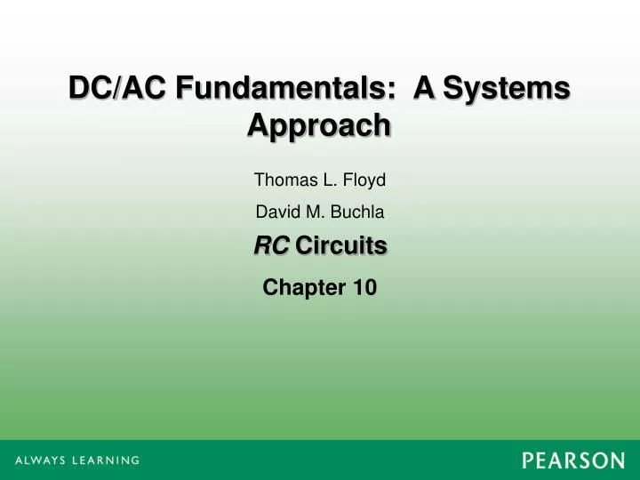
DC/AC Fundamentals: A Systems Approach. RC Circuits. Thomas L. Floyd David M. Buchla. Chapter 10. Ch.10 Summary. Sinusoidal Response of RC Circuits.

E N D
DC/AC Fundamentals: A Systems Approach RC Circuits Thomas L. Floyd David M. Buchla Chapter 10
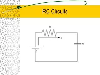
Ch.10 Summary Sinusoidal Response of RC Circuits When resistance and capacitance are connected in series, the phase angle between the applied voltage and total current is between 0 and 90, depending on the values of resistance and reactance.
Ch.10 Summary Impedance of Series RC Circuits In a series RC circuit, the total impedance is the phasor sum of R and XC. R is plotted along the positive x-axis. XC is plotted along the negative y-axis. Z is the diagonal It is convenient to reposition the phasors so they form an impedance triangle.
Ch.10 Summary Impedance of Series RC Circuits Sketch the impedance triangle and show the values for R = 1.2 kW and XC = 960 W.
Ch.10 Summary Series RC Circuit Analysis Ohm’s law is applied to series RC circuits using Z, V, and I. Because I is the same everywhere in a series circuit, you can obtain the various component voltages by multiplying the impedance of that component by the current, as the following example demonstrates.
Ch.10 Summary Series RC Circuit Analysis x 10 mA = Assume the current in the previous example is 10 mA. Sketch the voltage phasor diagram. (The impedance triangle from the previous example is shown for reference.) The voltage phasor diagram can be found using Ohm’s law. Multiply each impedance phasor by 10 mA (as shown below):
Ch.10 Summary Phase Angle vs. Frequency Reactance phasors can only be drawn for a single frequency because X is a function of frequency. As frequency changes, the impedance triangle for an RC circuit changes as illustrated here because XC decreases with increasing f. This determines the frequency response of RC circuits.
Ch.10 Summary Application A series RC circuit can be used to produce a phase lag by a specific amount between an input voltage and an output by taking the output across the capacitor. This circuit is a basic low-pass filter, a circuit that passes low frequencies and rejects all others. This filter passes low frequencies up to a frequency called the cutoff frequency.
Ch.10 Summary Application Reversing the components in the previous circuit produces a circuit that is a basic lead network. This circuit is a basic high-pass filter, a circuit that passes high frequencies and rejects all others. This filter passes high frequencies down to a frequency called the cutoff frequency.
Ch.10 Summary Application An application showing how a phase-shift network is useful is the phase-shift oscillator, which uses a combination of RC networks to produce a 180o phase shift that is required for the oscillator to work.
Ch.10 Summary AC Response of Parallel RC Circuits Conductance is the reciprocal of resistance. Capacitive susceptance is the reciprocal of capacitive reactance. Admittance is the reciprocal of impedance. For parallel circuits, it is useful to introduce two new quantities (susceptance and admittance) and to review conductance.
Ch.10 Summary AC Response of Parallel RC Circuits In a parallel RC circuit, the admittance phasor is the sum of the conductance and capacitive susceptance phasors: From the diagram, the phase angle is:
Ch.10 Summary AC Response of Parallel RC Circuits Draw the admittance phasor diagram for the circuit. The magnitudes of conductance, susceptance, and admittance are:
Ch.10 Summary Analysis of Parallel RC Circuits Ohm’s law can be applied to parallel RC circuits using Y, V, and I. Because V is the same across all components in a parallel circuit, you can obtain the current in a given component by simply multiplying the admittance of the component by the voltage, as illustrated in the following example.
Ch.10 Summary Analysis of Parallel RC Circuits If the voltage in the previous example is 10 V, sketch the current phasor diagram. The admittance diagram from the previous example is shown below for reference. The current phasor diagram can be found from Ohm’s law. Multiply each admittance phasor by 10 V.
Ch.10 Summary Phase Angle of Parallel RC Circuits As frequency increases, BC and IC must also increase, so the angle between IR and IS must increase. Notice that the formula for capacitive susceptance is the reciprocal of capacitive reactance. Thus BC and IC are directly proportional to f:
Ch.10 Summary Equivalent Series and Parallel RC Circuits For every parallel RC circuit there is an equivalent series RC circuit at a given frequency. The equivalent resistance and capacitive reactance are shown on the impedance triangle:
Ch.10 Summary Series-Parallel RC Circuits For example, the components in the green box are in series: The components in the yellow box are in parallel: Series-parallel RC circuits are combinations of both series and parallel elements. These circuits can be solved by methods from series and parallel circuits. The total impedance can be found by converting the parallel components to an equivalent series combination, then adding the result to R1 and XC1 to get the total reactance.
Ch.10 Summary Measuring Phase Angle An oscilloscope is commonly used to measure phase angle in reactive circuits. The easiest way to measure phase angle is to set up the two signals to have the same apparent amplitude and measure the period. An example of a Multisim simulation is shown, but the technique is the same in lab. Set up the oscilloscope so that two waves appear to have the same amplitude as shown. Determine the period. For the wave shown, the period is
Ch.10 Summary Measuring Phase Angle (Cont’d) Next, spread the waves out using the SEC/DIV control in order to make an accurate measurement of the time difference between the waves. In the case illustrated, the time difference is The phase shift is calculated from 55o
Ch.10 Summary The Power Triangle x 10 mA = As shown earlier, you can multiply the impedance phasors for a series RC circuit by the current to obtain the voltage phasors. The earlier example is shown below for review: Multiplying each value in the left-hand triangle gives you the corresponding value in the right-hand triangle.
Ch.10 Summary The Power Triangle (Cont’d) Multiplying the voltage phasors by Irms (10 mA) gives the power triangle values (because P = VI ). Apparent power is the product of the magnitude of the current and magnitude of the voltage and is plotted along the hypotenuse of the power triangle.
Ch.10 Summary Power Factor Power factor is the ratio of true power (in W) to apparent power (in VA). Volt-amperes multiplied by the power factor equals true power. Power factor can be determined using: Power factor can vary from 0 (for a purely reactive circuit) to 1 (for a purely resistive circuit).
Ch.10 Summary Apparent Power Apparent power consists of two components; the true power component, which does the work, and a reactive power component, that is simply power shuttled back and forth between source and load. Some components such as transformers, motors, and generators are rated in VA rather than watts.
Ch.10 Summary RC Circuit Frequency Response When a signal is applied to an RC circuit, and the output is taken across the capacitor as shown, the circuit acts as a low-pass filter. As the frequency increases, the output amplitude decreases. Plotting the response:
Ch.10 Summary RC Circuit Frequency Response Reversing the components, and taking the output across the resistor as shown, the circuit acts as a high-pass filter. As the frequency increases, the output amplitude also increases. Plotting the response:
Ch.10 Summary Key Terms Impedance The total opposition to sinusoidal current expressed in ohms. The angle between the source voltage and the total current in a reactive circuit. Phase angle Capacitive susceptance (BC) The ability of a capacitor to permit current; the reciprocal of capacitive reactance, measured in siemens (S). Admittance (Y) A measure of the ability of a reactive circuit to permit current; the reciprocal of impedance, measured in siemens (S).
Ch.10 Summary Key Terms The relationship between volt-amperes and true power or watts. Volt-amperes multiplied by the power factor equals true power. Power factor Frequency response In electric circuits, the variation of the output voltage (or current) over a specified range of frequencies. Cutoff frequency The frequency at which the output voltage of a filter is 70.7% of the maximum output voltage.
Ch.10 Summary Quiz 1. If you know what the impedance phasor diagram looks like in a series RC circuit, you can find the voltage phasor diagram by a. multiplying each phasor by the current b. multiplying each phasor by the source voltage c. dividing each phasor by the source voltage d. dividing each phasor by the current
Ch.10 Summary Quiz 2. A series RC circuit is driven with a sine wave. If the output voltage is taken across the resistor, the output will • be in phase with the input. • lead the input voltage. • lag the input voltage. • none of the above
Ch.10 Summary Quiz 3. A series RC circuit is driven with a sine wave. If you measure 7.07 V across the capacitor and 7.07 V across the resistor, the voltage across both components is a. 0 V b. 5 V c. 10 V d. 14.1 V
Ch.10 Summary Quiz 4. If you increase the frequency in a series RC circuit, a. the total impedance will increase b. the reactance will not change c. the phase angle will decrease d. none of the above
Ch.10 Summary Quiz 5. Admittance is the reciprocal of a. reactance b. resistance c. conductance d. impedance
Ch.10 Summary Quiz 6. Given the admittance phasor diagram of a parallel RC circuit, you could obtain the current phasor diagram by a. multiplying each phasor by the voltage b. multiplying each phasor by the total current c. dividing each phasor by the voltage d. dividing each phasor by the total current
Ch.10 Summary Quiz 7. If you increase the frequency in a parallel RC circuit, a. the total admittance will decrease b. the total current will not change c. the phase angle between IR and IS will decrease d. none of the above
Ch.10 Summary Quiz 8. The magnitude of the admittance in a parallel RC circuit will be larger if a. the resistance is larger b. the capacitance is larger c. both a and b d. none of the above
Ch.10 Summary Quiz 9. The maximum power factor occurs when the phase angle is a. 0o b. 30o c. 45o d. 90o
Ch.10 Summary Quiz 10. When power is calculated from voltage and current for an ac circuit, the voltage and current should be expressed as a. average values b. rms values c. peak values d. peak-to-peak values
Ch.10 Summary Answers 1. a 2. b 3. c 4. c 5. d 6. a 7. d 8. d 9. a 10. b