Download
1 / 38
380 likes | 905 Vues
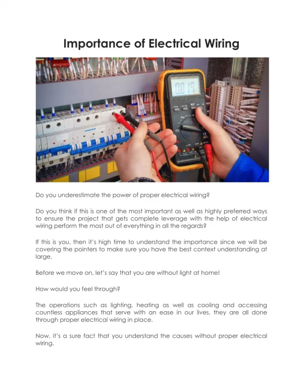
ELECTRICAL WIRING. WIRING BASICS. Written by Bobby Joslin. GA Ag Ed Curriculum Office To accompany the Georgia Agriculture Curriculum Lesson 01422-6.2 July 2002. STANDARDS FOR SAFETY. National Electrical Code Local Electrical Code Power Company Requirements Underwriters Laboratory (UL).

E N D
ELECTRICAL WIRING WIRING BASICS Written by Bobby Joslin GA Ag Ed Curriculum Office To accompany the Georgia Agriculture Curriculum Lesson 01422-6.2 July 2002
STANDARDS FOR SAFETY • National Electrical Code • Local Electrical Code • Power Company Requirements • Underwriters Laboratory (UL)
NATIONAL ELECTRICAL CODE • History of the National Electrical Code • Purpose of the NEC • How Often the NEC is updated • Scope of the NEC • Enforcement of the NEC • Using the NEC
LOCAL ELECTRICAL CODES • Local authorities may adopt NEC • May adopt NEC with modifications • Local wiring permits and inspections
UNDERWRITERS LABORATORY • UL Listed assures product meets minimum safety standards • UL Listed does not mean that product is safe for all installations • UL Listed is not an indication of quality
BRANCH CIRCUITS • Definition of circuit • Definition of branch circuit
BRANCH CIRCUITS IN A RESIDENCE • Individual Circuit • Small Appliance Circuit • Laundry Circuit • Bathroom Circuit • General Purpose Circuit
INDIVIDUAL CIRCUIT • Supplies only one outlet or piece of equipment • Motors 1/2 horsepower or larger • All 240 volt equipment • Other equipment such as furnace fan, freezer, television, computer
SMALL APPLIANCE CIRCUIT • Serves receptacles for small appliance loads • At least two required by NEC • Must be 20 ampere circuits • No lighting outlets • Cannot serve any other room in house
LAUNDRY CIRCUIT • Serves only receptacles in laundry room • At least one required by NEC • Must be 20 ampere circuit • May not have lighting outlets • May not serve outlets in any other room of house
BATHROOM CIRCUIT • Circuit to serve receptacles in bathroom • At least one required by NEC • Must be 20 ampere circuit • May not serve lighting outlets • May not serve any other room in house
GENERAL PURPOSE CIRCUITS • Serve all lighting outlets in home • Serve all receptacles not on one of the other types of circuits • May be 15 or 20 ampere (20 ampere preferred) • Allow at least one general purpose circuit for every 500 square feet of floor space in house
Determining the Kind, Number and Location of Outlets and Switches in a Wiring System
Lighting Outlet Requirements • At least one wall switch controlled outlet in every habitable room in house • Stairways consisting of 6 or more steps must have lighting outlet that is wall switch controlled at both floor levels • Attics, underfloor space, utility room and basement requirements
RECEPTACLE OUTLET REQUIREMENTS • No point along the floor line in any wall space may be more than 6 feet from a receptacle in kitchen, family room, dining room, living room, den, sun room, bedroom, recreation room, or similar room • (Receptacles must be no farther than _____ feet apart.)
RECEPTACLE REQUIREMENTS • A receptacle must be installed at each kitchen and dining area counter space if the space is wider than 12 inches • No point along the wall line of a kitchen counter may be more than 24 inches from a receptacle • (Receptacles must be no farther than _____ inches apart)
RECEPTACLE REQUIREMENTS • At least one receptacle is required within 36 inches of the outside edge of each basin in bathrooms. • All receptacles in bathrooms must have ground fault circuit interrupter protection
RECEPTACLE REQUIREMENTS • At least one outdoor receptacle is required • All outdoor receptacles must have GFCI protection • Outdoor receptacles must be installed in waterproof boxes
RECEPTACLE REQUIREMENTS • At least one receptacle is required in the laundry area • At least one receptacle is required in a basement. All general use receptacles in an unfinished basement must have GFCI protection
RECEPTACLE REQUIREMENTS • At least one receptacle is required in hallways 10 feet or more in length • Effective January 1, 2002, all receptacles in a bedroom must have arc-fault circuit interrupter protection
RECOMMENDATIONS FOR OUTLETS AND SWITCHES • Receptacles should generally be located approximately above floor line • Receptacles preferably should be located near the ends of wall space • Lighting outlets in closets should be wall switch controlled • Pull chain lighting outlets should be minimized, if used at all
RECOMMENDATIONS FOR OUTLETS AND SWITCHES • Wall switches should be generally be located approximately 48 inches above the floor line and on the latch side of doors • Three and four way switches should be used to control lights in locations such as rooms having more than one entrance, stairways, halls, basement, covered walkways between the house and garage, etc.
Determining the Number of Outlets On a General Purpose Circuit • For calculation purposes, estimate a load of at least 1.5 amps per outlet on the circuit • To determine the maximum number of outlets on a 20 amp general purpose circuit: 20 amps (circuit rating) 1.5 amps = 13 outlets (maximum) on the circuit • Maximum number of outlets on a 15 amp general purpose circuit = ________?
SELECTING SERVICE ENTRANCE EQUIPMENT • Service conductors • Service mast • Entrance head or weather head • Meter base • Service entrance cable
Service Entrance Panel • Purpose • Factors to consider when selecting the service entrance panel • Type of panel • Size or ampere rating • Circuit capacity or number of spaces for connecting circuits
PROVIDING OVERCURRENT PROTECTION • Providing a means to interrupt an electrical circuit when the amperage in the circuit becomes excessive • Reasons for providing overcurrent protection
PLANNING ELECTRICAL CIRCUITS • Wiring symbols
CLASSIFICATION OF CONDUCTORS • Grounded conductor • Ungrounded conductor • Equipment grounding conductor • Grounding electrode conductor
Grounded Conductor • A current carrying conductor that is connected to the earth • Often called the neutral wire • Color must be white or natural gray • Known as identified conductor • Identity must be maintained throughout a circuit and the electrical system
Grounded Conductor • NEVER connected to a fuse, circuit breaker, or a switch • One grounded conductor must be connected to all 120 volt outlets or equipment
UNGROUNDED CONDUCTOR • A current carrying conductor that is not connected to the earth • Often called the “hot” wire • Color should not be white, gray, or green. Color may be black, red, blue, etc. • Circuit breakers (or fuses) and switches are placed on the ungrounded conductor
UNGROUNDED CONDUCTOR • One ungrounded conductor must be connected to all 120 volt outlets or equipment. • Two ungrounded conductors must be connected to all 240 volt outlets or equipment.
EQUIPMENT GROUNDING CONDUCTOR • Under normal conditions, the equipment grounding conductor is never a current carrying conductor. It serves as a path to ground if a fault occurs in electrical equipment or the electrical system • May be a bare wire or may have green or green with yellow stripe insulation
EQUIPMENT GROUNDING CONDUCTOR • Always connected to the grounding terminal of devices (receptacles, switches, etc.) • Always connected to non-current carrying metal parts of equipment and circuits (including all metal boxes)
GROUNDING ELECTRODE CONDUCTOR • The large bare copper wire that connects the electrical system to the grounding electrode • Size is determined by the size of service entrance cable being used
COLOR CODING OF ELECTRICAL CONNECTIONS • Silver or white colored terminal - attach the grounded conductor • Copper or brass colored terminal -attach the ungrounded conductor • Green colored terminal - attach the equipment grounding conductor