Download
1 / 33
340 likes | 440 Vues
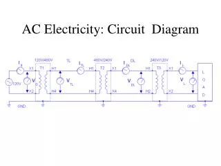
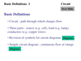
Circuit electricity. Atomic structure. Atoms are composed of protons (+), electrons (-) and neutrons. The nucleus contains the protons and neutrons and the electrons surround the nucleus. Atomic structure.

E N D
Atomic structure Atoms are composed of protons (+), electrons (-) and neutrons. The nucleus contains the protons and neutrons and the electrons surround the nucleus.
Atomic structure The outer layer of electrons in a metal is incomplete which allows them to pass from atom to atom
Atomic structure Because electrons can pass from atom to atom. charge can pass through a conducting material such as a metal. Metals are conductors
Atomic structure Some materials such as rubber and plastic have complete outer layers of electrons so they cannot pass from atom to atom. Charge cannot pass through these materials. These are called Insulators
Current Because it is the electrons which move from atom to atom in reality negative charge flows from negative to positive. This has the same effect as positive charge moving from positive to negative Conventional current flows from positive to negative
The Ampere (Named after Andre Marie Ampere) The Ampere is a measure of how much electrical current is flowing and is measured in units of amps QI = ---- t I = amps Q = charge (in coulombs) and t = time ( in seconds)
Potential Difference or Voltage Alessandro Volta Potential difference, or voltage, is the electrical potential energy per coulomb of charge. EV = ----Q V = voltage E = energy in Joules Q = charge (in coulombs)
Resistance Georg Ohm Resistance is a measure of opposition to the flow of charge and is measured in ohms () VI = ---- R I = current V = voltage R = resistance in ohms
Ohms Law (three versions) VI = ---- R V = IR VR = ----I
Electrical Power Power is the rate of using energy in joules per second P = E t or E = Pxt
Electrical Power From previous slides we know that EV = ---- Q QI = ---- t and
Electrical Power Combine the two and cancel the Q from each EV = ---- Q QI = ---- t X Leaving E/t so electrical power is P = V x I
Electrical Power Equation variations P = V x I P = I2R P = V2/R These were obtained by using Ohm’s law to substitute for V and I
Kirchoff’s Laws Kirchoff’s first Law The total current flowing into a junction is the total current flowing out of the circuit I2 I1 I3 I1 = I2 + I3
Kirchoff’s Second Law 1. The sum of the potential differences around an electrical circuit equals the supply voltage.
Resistors in series The total resistance is found by simply adding the resistance of each R1 + R2 +R3etc
Resistors in series The supply voltage (pd) is shared across the resistors. The voltage across each depends on the resistance of each
The current in a series circuit is the same all the way round the circuit (as per Kirchoff’s first Law). Current flowing into the resistor is the same as the current flowing out of the resistor) Resistors in series
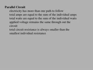
Resistors in parallel The total resistance is calculated as below
Resistors in parallel • The current in a parallel circuit is shared between each resistor. (The amount in each depends on the resistance)
Resistors in parallel • The supply voltage (pd) across each resistor is the same as the supply voltage
Combined resistors To calculate the total resistance of the circuit calculate the parallel set first and treat it as a single resistor in series with the other resistor
Example From the following diagram determine: a) Total resistance. b) Total (supply) current. c) Voltage across each resistor. d) Power loss in resistor R1. R1 = 50Ω, R2 = 100Ωand supply voltage = 12V.
Example Total resistance = R1 + R2 =150Ω Total (supply) current V/I = 12/150 =0.08 amps. Voltage across R1 = 50 x 0.08 = 4 volts Voltage across R2 = 100 x 0.08 = 8 volts Power loss in R1 = V x I = 4 x 0.08 = 0.32 Watts R1 = 50Ω, R2 = 100Ωand supply voltage = 12V.
Example From the following diagram determine: a) Total resistance. b) Total (supply) current. c) Current through each resistor. R1 100Ω, R2 = 1kΩand supply voltage = 12V.
Example 1/Total resistance = 1/100 +1/1000.= 10/1000 + 1/1000 = 11/1000 Total resistance = 1000/11 =90.9Ω
Example Total current = V/R = 12/90.9 = 0.132 amps Current through R1, V/R1 = 12/100 = 0.12 amps Current through R2, V/R2 = 12/1000 = 0.012 amps
Example From the diagram below, determine: a) The total resistance, and the supply current. b) The voltage across the R1 resistor. c) The current through R2 , and the power dissipated in it. R1 = 200Ω R2 and R3 are both 100Ω and the supply voltage is 12 volts
Example Resistance of the parallel resistors 1/total = 1/100 +1/100 =2/100 Total resistance = 100/2 = 50Ω Total resistance in circuit = 200+50 = 250Ω Current = V/R =12/250 =0.048 amps
Example Voltage across R1 I x R =0.048 x 200 = 9.6 volts
Example Voltage across R1 & R2 V = I x R 0.048 x 50 = 2.4 volts Current through R2 I = V/R =2.4/100 =0.024amps
Example Power dissipated P = V x I 2.4 x 0.024 = 0.058 watts