Download
1 / 11
110 likes | 320 Vues
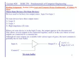
Input A. Output Y = . A if C = 1 High Z if C = 0. Control C. Tri-state buffer. Lecture #20 EGR 270 – Fundamentals of Computer Engineering. Reading Assignment: Section 2.10 in Logic and Computer Design Fundamentals, 4 th Edition by Mano. Three-State Devices (Tri-State Devices)

E N D
Input A Output Y = A if C = 1 High Z if C = 0 Control C Tri-state buffer Lecture #20 EGR 270 – Fundamentals of Computer Engineering Reading Assignment: Section 2.10 in Logic and Computer Design Fundamentals, 4th Edition by Mano • Three-State Devices (Tri-State Devices) • Devices used so far have two output states: logic 0 or logic 1 • Tri-state devices have three output states: • Logic 0 • Logic 1 • High impedance (Z) state • When a tri-state device is in the high Z state, the output appears to be disconnected. This allows several outputs to be connected together, such as in the case where several outputs are connected to a common bus. • Although tri-state outputs are available with various types of gates, the most common is probably the tri-state buffer.
Lecture #20 EGR 270 – Fundamentals of Computer Engineering
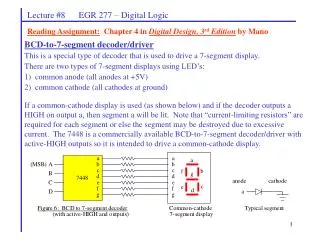
Lecture #20 EGR 270 – Fundamentals of Computer Engineering Octal 3-state buffer: Reference: John Wakerly, Digital Design – Principles & Practices, 3rd Edition, Prentice-Hall
1 0 0 1 4-bit bus 0 1 1 0 Z Z Z Z Z Z Z Z 0 1 0 0 1 0 1 0 1 0 1 1 1 0 0 Bus Controller Device 1 Device 2 Device 3 Lecture #20 EGR 270 – Fundamentals of Computer Engineering Application: Connecting several peripheral devices to a bus Can be used to indicate when certain counts occur. Similarly, they can be used to start or stop events at certain times. Note in the example below that the bus controller connects Device 2 to the bus and Devices 1 and 3 are in the high-Z state.
Lecture #20 EGR 270 – Fundamentals of Computer Engineering Rather than show each wire in a bus, it is more convenient to show a bus as follows: 8 Notation for an 8-bit bus The last diagram repeated using bus notation: 4 1 Z Z 4 4 4 0 0 1 Bus Controller Device 1 Device 2 Device 3
Lecture #20 EGR 270 – Fundamentals of Computer Engineering Application: Using two 74541 IC’s to connect two 8-bit user inputs to a common data bus (DB) connected to a microprocessor Reference: John Wakerly, Digital Design – Principles & Practices, 3rd Edition, Prentice-Hall
Lecture #20 EGR 270 – Fundamentals of Computer Engineering Transceiver - A device capable of transferring information in either direction. A transceiver can be constructed using two tri-state buffers along with some control logic, as shown below. A B Enable Direction Enable 0: enable transceiver 1: disable transceiver Direction 0: transfer A to B 1: transfer B to A Buffer Control Lines 1: enable buffer 0: disable buffer (high Z)
A A A B B B Enable Enable Enable Direction Direction Direction Lecture #20 EGR 270 – Fundamentals of Computer Engineering Illustration – Add logic values to the diagrams below to illustrate the transceiver operation. Case 1: Enable = 1 Case 2: Enable = 0 Direction = 0 Case 3: Enable = 0 Direction = 1
Lecture #20 EGR 270 – Fundamentals of Computer Engineering Octal 3-state transceiver: Reference: John Wakerly, Digital Design – Principles & Practices, 3rd Edition, Prentice-Hall
Figure 5-60 Bidirectional buses and transceiver operation. Lecture #20 EGR 270 – Fundamentals of Computer Engineering Application: Octal 3-state transceiver used to connect two data buses: Reference: John Wakerly, Digital Design – Principles & Practices, 3rd Edition, Prentice-Hall
Lecture #20 EGR 270 – Fundamentals of Computer Engineering Tri-state outputs with PLD’s: Recall that the GAL22V10 PLD was discussed earlier. It has 22 Output Logic MacroCells (OLMCs) that can be configured as inputs or outputs. How is this possible? By using tri-state buffers.