Download
1 / 20
390 likes | 1.09k Vues
Digital Communications. EE549/449 FALL 2001 Lecture #26 Pulse Shaping Controlled Intersymbol Interference Wednesday October 24, 2001. Root Raised Cosine (RC) rolloff Pulse Shaping.

E N D
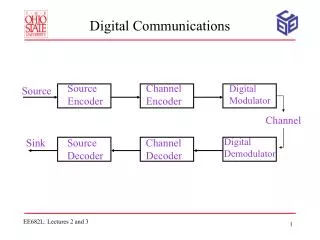
Digital Communications EE549/449 FALL 2001 Lecture #26 Pulse Shaping Controlled Intersymbol Interference Wednesday October 24, 2001
Root Raised Cosine (RC) rolloff Pulse Shaping • We will see later in the semester that the noise is minimized at the receiver by using a matched filter • If the transmit filter is H(f), then the receive filter should be H*(f) • The combination of transmit and receive filters must satisfy Nyquist’s first method for zero ISI • Transmit filter with the above response is called the root raised cosine rolloff filter • Root Raised Cosine rolloff pulse shapes are used in many applications such as US Digital Cellular, IS-54 and IS-136
Practical Issues with Pulse Shaping • Like the Sa(.) pulse, RC rolloff pulses extend infinitely in time • However, a very good approximation can be obtained by truncating the pulse • E.g., we can make h(t) extend from -3Tb to +3Tb • RC rolloff pulses are less sensitive to timing errors than Sa(.) pulses • Larger values ofare more robust against timing errors • US Digital Cellular (IS-54 & IS-136) uses root RC rolloff pulse shaping with = 0.35 • IS-95 uses pulse shape that is slightly different from RC rolloff shape • European GSM uses Gaussian shaped pulses
Implementation of Raised Cosine Pulse: • Practical pulses must be truncated in time • Truncation leads to sidelobes - even in RC pulses • Can be digitally implemented with an FIR filter • Analog filters such as Butterworth filters may approximate the tight shape of this spectrum • Sometimes a “square-root” raised cosine spectrum is used when identical filters are implemented at transmitter and receiver • This has to do with matched filtering
Controlled ISI • To achieve zero ISI, we have seen that it is necessary to transmit at below the Nyquist rate • Is it possible to relax the condition on zero ISI and allow for some amount of ISI in order to achieve a rate > 2B? • Idea is to introduce some controlled amount of ISI instead of trying to eliminate it completely • ISI that we introduce is deterministic (or controlled) and hence we can take care of it at the receiver • How do we do this? • Controlled amount of ISI is introduced by combining a number of successive binary pulses prior to transmission • Since the combination is done in a known way, the receiver can be designed to correctly recover the signal • We will now discuss different methods of controlled ISI
Partial Response Signaling (PRS) • Also known as Doubinary signaling, Correlative coding, Polybinary • PRS is a technique that deliberately introduces some amounts of ISI into the transmitted signal in order to ease the burden on the pulse-shaping filters • It removes the need to strive at achieving Nyquist filtering conditions, and high rolloff factors • This strategy involves two key operations • Correlative Filtering (CF) • Digital Precoding (DP) • CF purposely introduces some ISI, resulting in a pulse train with higher amplitude levels and correlated amplitude sequences • Nyquist rate no longer applies since the correlated symbols are no longer independent • Hence higher signaling rate can be used
The transfer function H(f) is equivalent to the Tap Delay Line model
Since h(t) = sinc(t/T) and R=1/T, the overall impulse response is and where • PRS changes the amplitude sequence ak a+k • a+k has a correlated amplitude span of N symbols since each a+k depends on the previous N values of ak • Also, when ak has M levels, a+k sequence has M+ > M levels • A whole family of PRS methods exists • Lets look at a few specific cases of PRS
Duobinary Signaling • Also called class 1 signaling • Simplest form of PRS with M = 2, N = 1, Co = C1 = 1 • The input data sequence is combined with a 1-bit delayed version of the same sequence (the controlled ISI) and then passed through the pulse-shaping filter • Duobinary Encoder
Each incoming pulse is added to the previous pulse • The bit or data sequence {yk} are not independent • Each yk digit caries with it the memory of the prior digit • It is this correlation between digit that is considered the controlled ISI which can be easily removed at the receiver • Impulse Response of Duobinary Signal:
From it can be shown that (exercise - show this) • Impulse response h(t) for the duobinary scheme is simply the sum of two sinc waveforms, delayed by one bit period w.r.t each other:
Duobinary signaling can be interpreted as adjacent pulse summation followed by rectangular low pass filtering • Encoder takes a 2 level waveform and produces a 3 level waveform • Duobinary Decoding: • The role of the receiver is to recover xk from yk • Transmitted signal (assuming no noise) is • xk can assume one of 2 values A, depending on whether the k-th bit is 1 or 0 • Since yk depends on xk and xk-1, yk can have 3 values (no noise)
In general, (M-ary transmission), PRS results in 2M-1 output levels • Detection involves subtracting xk-1 decisions from yk digits such that • The detection process is the reverse operation at the transmitter • Decision rules is • A major drawback to this technique is that once errors are made, they tend to propagate through the system
A Duo-binary Baseband System • Advantage: • It permits transmission at the Nyquist rate without the need for linear phase rectangular pulse shaping • Disadvantages: • There is no one to one mapping between detected ternary symbol and the original binary digits (2 3)
Require more power • Ternary nature of duobinary signal requires about 3 dB greater SNR compared to ideal signaling (i.e, binary) for a given PB • The decoding process results in propagation of errors • Because output data bits are decoded using previous data bit, if it is in error then the new output will be in error, and so on • In other words, errors will propagate through the system • It is ineffective for AC coupled signal • PSD has substantial values at zero making it unsuitable for use with AC coupled transmission Note: • Problem 3 can be solved by a technique known as precoding • Problem 4 is solved by a technique known as modified duobinary
Summary of Duobinary Baseband System • In general, (M-ary transmission), PRS results in 2M-1 output levels • Detection involves subtracting xk-1 decisions from yk digits such that • Decision rules is
Composite pulses arising from like and unlike combinations of input impulse pair
Example 30: (Duobinary Coding) (See example 2.4) • Binary sequences xk 0 0 1 0 1 1 0 • Amplitude: ak 1 -1 -1 1 -1 1 1 -1 • Coding Rule: • Decoding Rule: • Output sequence