Download
1 / 26
320 likes | 376 Vues
1. 2. 1. 5. 3. 2. 4. 4. 3. 5. Plant, Machine & Office Layout. Definition : The physical positioning of processes, departments, equipment and work areas to optimize an organization’s effectiveness in achieving its operating objectives. Traditional Production Layout. Batch Production.

E N D
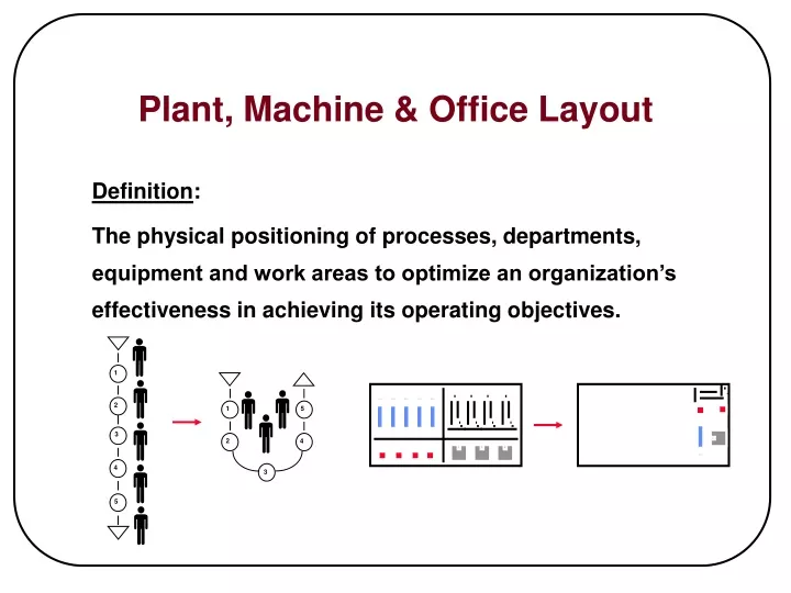
1 2 1 5 3 2 4 4 3 5 Plant, Machine & Office Layout Definition: The physical positioning of processes, departments, equipment and work areas to optimize an organization’s effectiveness in achieving its operating objectives.
Traditional Production Layout Batch Production Mill Lathe Scheduled Inventory Scheduled Inventory Stock Room • Departments Organized by Function • Inventory Banks Before/After Each Process • Large Batch Sizes • Equipment (e.g. Fork Trucks) Required to Move Material • Resource(s) required to maintain Stock Room • Lead Times are Long • High Inventory • Each Area Optimizes it's own Performance • Processing Time is a Small % of Total Time
Traditional LayoutDepartmental Focus Entrance A A B B B A 1 2 3 COMMON ACTIVITY 4 Exit 7 6 C C D D D C 5
Traditional Process Flow 1 1 1 2 2 3 3 3 3 • Complex Material Flow • Complex Scheduling Required • Large Inventories within System • Long Lead Times • Batch Operations • High Cost to Manufacture
x x x x Conveyor x x x x • Work Paced by Conveyer • Material Handling Reduced • Individual Station Disruptions Accumulate • High Capital Investment • Low Flexibility to Satisfy Schedule Variations • Usually Long Changeover Times Traditional Production LayoutAssembly Line
Continuous Flow Process ( i.e. Paint or Plating) • Raw Materials Stored Externally to Process • Complicated Scheduling • Fork Trucks Required to Move Material • Material Moved Long Distances • Resource(s) Required for Stock Rooms • Packaging often done External to Dept. • High Inventories • Long Lead Times Finished Goods Storage Raw/WIP Stock Room Traditional Production Layout"Process Flow"
Layout Waste Elimination Techniques • Group Technology • Point of Use Manufacturing • Cell Technology
Grouping of Operations so that the End of One Operation is Located at the Start of the Next Operation Layout Waste Elimination Techniques Group Technology
1 1 1 2 2 2 3 3 3 3 Layout Waste Elimination TechniquesGroup Technology • Processes Grouped by Product Families • Simplified Material Flow • Simplified Scheduling • Small Batch Sizes between Processes • Shortened Lead Times • Lower Cost to Manufacture
Layout Waste Elimination Techniques Point of Use Manufacturing • Locate Feeder and User Operations Adjacent • to Each Other at the Assembly Line or • Manufacturing Cell. Feeder Operation x x x x x Conveyor x x x x
Entrance C A B Operator 1 Operator 2 Exit E D F Layout Waste Elimination Techniques Cell Technology • Operations are located so that one individual • can produce the entire assembly - with multiple • simple machines instead of one large machine.
Flexibility to Increase/Decrease Number of Operators depending on Schedule No Fork Trucks, Dedicated Material Handlers or Stockrooms Required Eliminates Large Inventories between Operations Grouping Technology Reduces Product Variation Better Control of Quality between Operations Entrance C A B Operator 1 Operator 2 Exit E D F Layout Waste Elimination Techniques Layout Using Manufacturing Cell Concept:
“U” or other Shape for Equipment Layout; (1) Operator could produce entire Product Multiple Simple Machines; not One Large Machine Operators Know Every Job and Rotate between Jobs Vary Amount of Personnel within Cell to Match Schedule Requirements Layout Waste Elimination Techniques Cell Concept
C B B A A A B C Common Activity Operator A Operator B D A E B E D Layout Waste Elimination Techniques Manufacturing Cells; Including a Monument
D C A B LEAN ORGANIZATION CELLS MANY SHAPES AND SIZES Equal Sign Shaped S - Shaped A B C C B C C D D C U - Shaped A C P D D A P C
A 1 LESS WAITING INVENTORY INCREASES UN-BALANCED 2 3 A A A B LEAN ORGANIZATION CELLS INTERIM STEPS BIRD CAGE PRODUCT FOCUS SMOOTHER FLOW BALANCING DIFFICULT REALLOCATION DIFFICULT 1 ISOLATED ISLANDS 2 3 C
LEAN ORGANIZATION CELLS COMBINED CELLS 6 PARTS 1 3 2 3 4 5 part D part C 1 2 4 3 4 2 9 8 5 6 7 5 8 1 6 7 6 17 16 18 3 4 15 1 7 1 7 1 2 5 14 9 8 2 10 6 2 part E part A part B 13 6 13 9 3 5 part F 9 11 8 7 10 12 8 4 4 7 5 6
1 2 3 3 4 5 2 3 4 1 4 2 9 8 5 6 5 7 1 8 7 6 18 17 16 6 3 4 15 7 1 7 1 5 14 1 2 8 9 10 2 6 2 13 6 9 3 3 5 10 12 11 7 9 8 4 4 8 5 7 6 LEAN ORGANIZATION CELLS COMBINED CELLS 1 MINUTE CYCLE- 8 WORKERS
1 2 3 3 4 5 2 3 4 1 4 2 9 8 5 6 5 7 1 8 7 6 18 17 16 6 3 4 15 7 1 7 1 5 14 1 2 8 9 10 2 6 2 13 6 9 3 3 5 10 12 11 7 9 8 4 4 8 5 7 6 LEAN ORGANIZATION CELLS COMBINED CELLS 1.2 MINUTE CYCLE - 6 WORKERS
More Machines than People; Operators should Run More than One Machine. Keep Large Containers Out of Cell No Physical Barriers within Cell; e.g. Control Panels, Tool Boxes, etc. Arrange Machines Close Enough together to Allow Operators to Operate Machines on Both Sides of Cell. Operators Should Perform Material Handling between Machines; Minimum or Single Parts. U Cell Guidelines for Waste Elimination
1st and Last Operation should be done by Same Operator (Where Feasible) OK for Operators to Walk between Stations (unless Excessive); Machines can wait on People Total Operator Work Content should not Equal 100 % of Demand Cycle Time to Allow for: Material Handling Preventative Maintenance Changeovers U Cell Guidelines for Waste Elimination (Continued)
Eliminate Need for Function (Best Alternative) Combine Operations where possible (Next Best) reduces inventory between processes reduces excessive operator motions/ walking enhances operator productivity Utilize Dedicated Equipment/Tools (where possible) Organize Operations by Product Flow Path (Group Technology) Incorporate Simple/Flexible Types of Equipment or Tooling Overall Layout Guidelines for Waste Elimination
Store Incoming Material at Point of Use. Design Containers to Fit Point of Use. Arrange Equipment so that Output of one Process is located at Input of Next Process. Design Layout for Standard Conditions; Don’t Institutionalize the Exceptions Overall Layout Guidelines for Waste Elimination -Continued
Receiving Shipping A S S E M B L Y FABRICATION FABRICATION FABRICATION Overall Layout Guidelines for Waste Elimination -Continued • Locate End of Assembly Line at Shipping Docks.
Overall Layout Guidelines for Waste Elimination -Continued • Use Simple Automation with Minimum Material Handling • Progression from Manual into Automation Simplify Consolidate Automate
Permits Immediate Feedback on Quality Problems Reduces Scrap and Obsolescence Saves Space and Investment in Material Handling and Capital Equipment Provides Greater Flexibility Eliminates Waste Improves Responsiveness to Customer Requirements Plant, Machine & Office Layout Benefits