Download
1 / 23
230 likes | 321 Vues
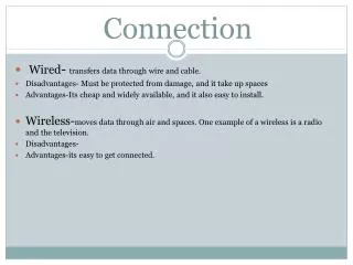
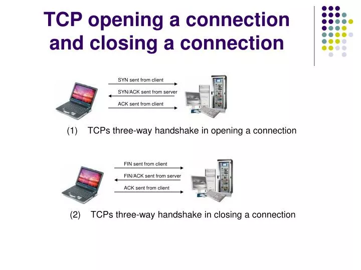
SYN sent from client. FIN sent from client. SYN/ACK sent from server. FIN/ACK sent from server. ACK sent from client. ACK sent from client. TCP opening a connection and closing a connection. (1) TCPs three-way handshake in opening a connection.

E N D
SYN sent from client FIN sent from client SYN/ACK sent from server FIN/ACK sent from server ACK sent from client ACK sent from client TCP opening a connection and closing a connection (1) TCPs three-way handshake in opening a connection (2) TCPs three-way handshake in closing a connection
Circuit Switching, Message Switching and Packet Switching Circuit Switching : Establishes end-to-end network path before any data is sent. Network path once set up, is not shared with other users. Other nodes have to wait until the transmission is over to the circuit to be released. Message Switching : No network path is established. Entire message is sent to the destination via network paths that are shared with other users. Congestions are likely to occur depending on the size of the message.
Circuit Switching, Message Switching and Packet Switching Packet Switching : No network path is established. Messages are broken down in to smaller size manageable packets before being sent. Packets are being sent to the destination over network paths shared with other traffic. Destination assembles the packets retrieving the original message. Virtual Circuit Switching : Packet switching network that emulates circuit switching by establishing a virtual circuit before the packets are sent. All the packets are delivered using the same virtual circuit.
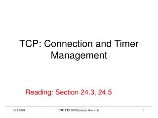
5 3 5 2 3 1 1 1 2 1 4 5 2 3 6 Question 13) Find the least cost path from node (1) to node (6) using forward search algorithm.
Network : Network is a set of interconnected computers Local Area Network : A computer network covering a small geographic area ( usually less than 1 km2 ) Wide Area Network : A computer network that covers a broad geographic area ( usually a collection of LANs ) Hub : A Hub is used in a wired network to connected Ethernet cables from number of workstations together. Data packets sent from one machine are connected to rest of the machines. The each machine check the header for the destination address. The intended machine retrieves the packet while other machines discard it. Hubs are prone to packet sniffing attacks. TCP dump/Net stumbler/ Wireshark(Ethereal) – A hub operates on layer 1 : physical layer Switch : A switch is a intelligent hub that forwards incoming frames to a specific port that will take data to its intended destination. Reads the intended MAC address from the received data frame and determines the forwarding port from the Switching Table and connect the received frame to the intended port. Switch operates on MAC sub layer of the layer 2 : the data link layer. A network switch constructs its switching table by extracting the source MAC address from the received frames. If the entry does not exist the switch will forward the frames to all its ports. Prone to ARP poisoning attacks. Cain and Able
Bridge : A bridge is used to partition busy networks into several collision domains. Bridge operates on the MAC layer, sub layer of the layer 2 (data link layer). Bridge reads the destination MAC address from the frame header and decides which partition the frame should be relayed to. Once switched on the bridge learns which computer is connected in each collision domain. The learning process occurs as the bridge encounters traffic. The bridge extracts the source MAC address from received frames to determine collision domain that the extracted MAC address is connected to and constructs a bridging table. If the bridging table doesn’t have an entry for the MAC address, bridge will forward the frame to all the domains connected. Computer B Router : A router is an internetworking device commonly used to connect different network types together. A router has two or more interface, each interface connecting a different network type and forwards packets according to its destination address. Router can be seen as a layer 3 switch (network layer ). Router accepts incoming packets from one network interface and forwards towards its intended destination. Routers are the basic building block holding the internet in place. Routers uses IP address instead of MAC addresses and constructs routing table from the received packets. Computer A
Modem : A modem is a communication device that converts one form of signal to another that is suitable for transmission over communication network such as telephone lines, typically from digital to analogue and from analogue to digital.
Sending time - Time to detect collision - Transmitted frame length - Propagation delay to frame length ratio - Number of retries needed - Therefore average time for transmitting one frame - Utilization factor -
Wireless LAN - A computer network covering a small geographic area that communicates with each other without wires (wireless) Advantages of wireless LAN - Increased mobility of users Increased flexibility Instant networking Availability of LAN technology Disadvantages of wireless LAN - Higher cost Lower performance Lower reliability Multiple standards Poor security (WEP-Wired Equivalent Privacy- open system authentication- no real authentication but clients need correct key to encrypt data, shared key authentication – shared key authentication can easily be cracked) WPA- Wifi Protected Access – can be cracked passively or actively. Needs several thousand authentication packets to crack pre shared key. Alternatively you send deauthentication signals to existing clients, forcing them to reauthenticate with the AP, accelerating the cracking process.
Criteria for LAN Design Functionality – Speed and Reliability, The network must work with reasonable speed and reliability Scalability – Ability to grow without major changes, The network must be able to grow without any major changes to the overall design Adaptability – Easily implements new technologies, The network should include no element that would limit the use of new technologies as they become available Manageability – Facilitates monitoring and ease of Management, The network must be able to allow ease of monitoring and managing
0 1 2 3 4 8 16 24 31 suffix 0 Class A prefix 0 suffix 1 Class B prefix suffix 1 prefix 0 1 Class C 0 1 1 1 Reserved for future use multicast address 1 1 1 1 Class D Class E IP addresses IP Address is 32 bits in length and consists of two parts, prefix denoting network id. and suffix denoting host id. Since internet might include networks including from few computers to hundreds of thousands we divide the 32 bit IP address space into three primary classes with different prefix and suffix sizes Net id Primary Classes
Multicast addresses : To use IP multicasting set of hosts must agree to share a multicast address. Once the multicast group has been established, a copy of any packet sent to the multicast address will be delivered to each host in the set. Although IP addresses are 4-octets, 32 bit numbers we generally represent each octet by its decimal value separated by a dot. This is known as dotted decimal notation. 32 bit binary number Dotted decimal notation 10000000 00001010 00000010 00000011 128 . 10 . 2 . 3 The class of the network must be identified from the first octet.
IP Address designing parameters Subnet Masking Rather than allocating address blocks in eight bit boundaries, which in certain cases could be a waste of address space, arbitrary prefix and suffix lengths are introduced using a subnet mask. Subnet mask is a 32 bit number in which left hand side ones correspond to prefix and right hand side zeros correspond to suffix. 10000000 00001010 00000010 00000011 IP Address 128.10.2.3 11111111 11111111 11111111 00000000 255.255.255.0 Subnet Mask This corresponds to a class C network Prefix – first 24 bits – 128.10.2. Suffix – last 8 bits - 3
CIDR : Classless Inter-Domain Routing Rather than allocating address blocks in eight bit boundaries forcing 8, 16, 24 bit prefixes, it uses arbitrary length prefixes. Prefix length in bits 192.168.0.3 / 16 CIDR Notation 32bit IP address Example :- Consider a private intranet of a large organization which consists of 4 physical networks. One small, two medium sized and one extremely large network. Design suitable IP address scheme. *** Medium sized network 2 Medium sized network 1 128.11.0.2 128.11.0.1 128.10.0.1 Large Network 128.10.0.2 Small network 10.10.0.1 10.10.0.2 192.168.0.2 192.168.0.1
ARP : Address Resolution Protocol ARP is the standard method of finding out hosts layer 2 MAC address when only its layer 3 IP address is known. If host ‘A’ needs to send a a data packet to host ’B’, host ‘A’ broadcasts ARP request packet containing ‘A’s MAC address. Host ‘B’ upon receiving the ARP request replies with its MAC address directly (unicast) to host ‘A’ while other stations discard the ARP request. Host ‘A’ now having the MAC address of host ‘B’ can directly send the data packet. RARP : Reverse Address Resolution Protocol RARP is the reverse process of ARP. It’s the process of finding out the layer 3 network address from layer 2 MAC address. RARP was subsequently replaced by DHCP. DHCP : Dynamic Host Configuration Protocol DHCP is a protocol used by clients to obtain various necessary parameters for its operation. DHCP allows clients to be configured automatically over the network. New machines can be added to the network more easily. Less chance of error. DNS : Domain Name System DNS associates domain names with difficult to remember IP address. Mapping domain name to an IP address is called domain name translation. When a host requires a domain name translation it makes a request to its assigned DNS server.
Aloha System ALOHA was a pioneering computer networking system developed at the University of Hawaii. Although the network itself is no longer used, the ALOHA project is quite important as one of the core concepts in the ALOHA net is the basis for widely used Ethernet technology. Aloha key concept : If you have data send data. If the message collides try resending the data later. The waiting time must be random or the same frames will collide over and over again, in a deadlock. N – Number of frames generated by all the users connected per frame time G – Total Number of frames generated per frame time (New and retransmitted) G≥ N G is also known as the channel traffic S – Channel throughput per frame time, number of successful transmission per frame time Channel throughput is equal to number of total packets generated in the system per given time into the probability of a frame does not suffer collision
Aloha Capacity S – Channel throughput per frame time, number of successful transmission per frame time Channel throughput is equal to number of total packets generated in the system per given time into the probability of a frame does not suffer collision P0 – Probability of a frame does not suffer collision If (number of users connected) → ∞, N and G takes the shape of Poisson distribution. P0 = e-2G S=G. P0 Therefore S = G.e-2G
Aloha Capacity S – Channel throughput per frame time, number of successful transmission per frame time Channel throughput is equal to number of total packets generated in the system per given time into the probability of a frame does not suffer collision P0 – Probability of a frame does not suffer collision If (number of users connected) → ∞, N and G takes the shape of Poisson distribution. P0 = e-2G S=G. P0 Therefore S = G.e-2G Capacity is the maximum throughput We can see the throughput is maximum at G = 0.5 S=0.5 x e-2x0.5 = 0.1839 The channel Utilization is Approximately 18%
Slotted Aloha Slotted Aloha divides the time into discrete time intervals, each interval corresponding to one frame time. Rather than trying to send data at any given time, users are forced to send data only at the beginning of a time slot. This minimises probability of collision and increase the channel throughput. The users must know the beginning of the time slot to begin transmitting data. The system uses a pilot signal to inform the workstations of the beginning of the time slot. S=G. P0 The channel throughput In slotted Aloha the probability of frame not colliding improves P0 = e-G Therefore S = G.e-G We can see the throughput is maximum at G = 1 Capacity is the maximum throughput S=1 x e-1 = .368 The channel Utilization is Approximately 37% The channel capacity doubles
Capacity is the maximum throughput We can see the throughput is maximum at G = 0.5 S=0.5 x e-2x0.5 = 0.1839 The channel Utilization is Approximately 18% If an ALOHA system has a total generated capacity of 14400 bits/s, a.) Compute the maximum capacity a pure ALOHA system can reach b.) Compute the maximum capacity a slotted ALOHA system can reach Pure ALOHA system has a utilization factor of 18%, and therefore can reach a maximum capacity of 14400x0.1839 = 2648 bits/s Pure ALOHA system has a utilization factor of 37%, and therefore can reach a maximum capacity of 14400x0.386 = 5558 bits/s