Download
1 / 160
1.62k likes | 1.74k Vues
Understanding Neutron Radiography Reading 2016-VI-ASTM-NRT-A

E N D
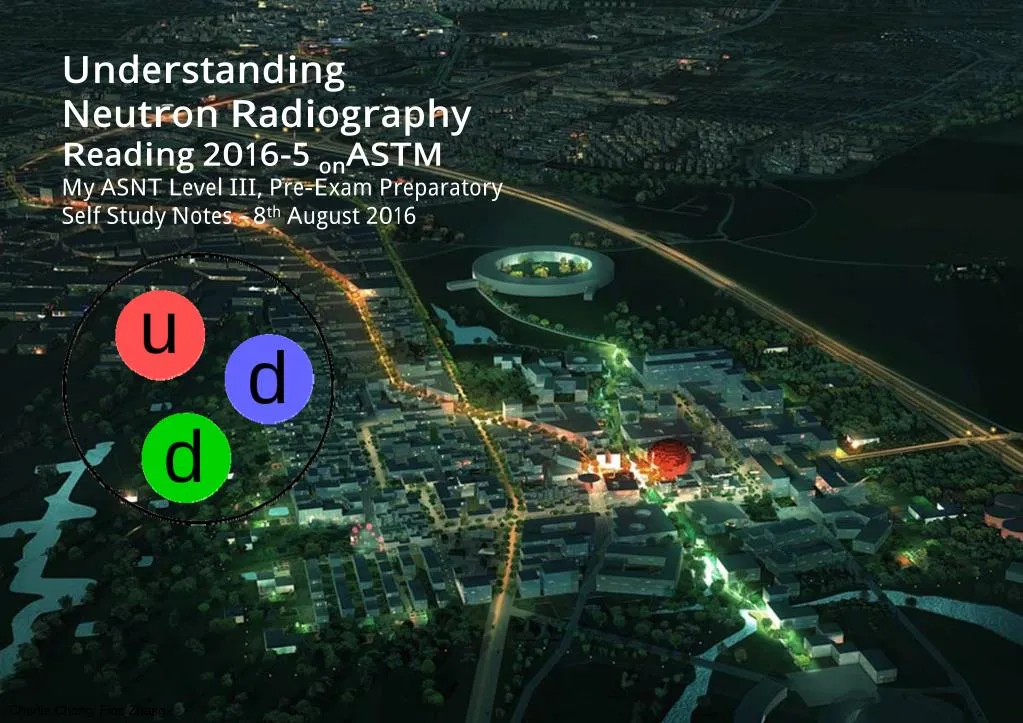
Understanding Neutron R adiography R eading 2016-5 onASTM My ASNT Level III, Pre-Exam Preparatory Self Study Notes - 8thAugust 2016 Charlie Chong/ Fion Zhang
SNS Facilities Charlie Chong/ Fion Zhang
SNS Facilities Charlie Chong/ Fion Zhang
The Magical Book of Neutron Radiography Charlie Chong/ Fion Zhang
数字签名者:Fion Zhang DN:cn=Fion Zhang, o=Technical, ou=Academic, email=fion_zhang@ qq.com, c=CN 日期:2016.08.08 21:38:54 +08'00' Charlie Chong/ Fion Zhang
ASNT Certification Guide NDT Level III / PdM Level III NR - Neutron Radiographic Testing Length: 4 hours Questions: 135 1. Principles/Theory • Nature of penetrating radiation • Interaction between penetrating radiation and matter • Neutron radiography imaging • Radiometry 2. Equipment/Materials • Sources of neutrons • Radiation detectors • Non-imaging devices Charlie Chong/ Fion Zhang
3. Techniques/Calibrations • Electron emission radiography • Blocking and filtering • Micro-radiography • Multifilm technique • Laminography (tomography) • Enlargement and projection • Control of diffraction effects • Stereoradiography • Panoramic exposures • Triangulation methods • Gaging • Autoradiography • Real time imaging • Flash Radiography • Image analysis techniques • In-motion radiography • Fluoroscopy Charlie Chong/ Fion Zhang
4. Interpretation/Evaluation • Image-object relationships • Material considerations • Codes, standards, and specifications 5. Procedures • Imaging considerations • Film processing • Viewing of radiographs • Judging radiographic quality 6. Safety and Health • Exposure hazards • Methods of controlling radiation exposure • Operation and emergency procedures Reference Catalog Number NDT Handbook, Third Edition: Volume 4, Radiographic Testing 144 ASM Handbook Vol. 17, NDE and QC 105 Charlie Chong/ Fion Zhang
Fion Zhang at St Petersburg 8thAugust 2016 Charlie Chong/ Fion Zhang Charlie Chong/ Fion Zhang
SME- Subject Matter Expert http://cn.bing.com/videos/search?q=Walter+Lewin&FORM=HDRSC3 https://www.youtube.com/channel/UCiEHVhv0SBMpP75JbzJShqw Charlie Chong/ Fion Zhang
http://greekhouseoffonts.com/ Charlie Chong/ Fion Zhang
Nuclear spallation occurs naturally in Earth's atmosphere owing to the impacts of cosmic rays, and also on the surfaces of bodies in space such as meteorites and the Moon. Evidence of cosmic ray spallation (also known as "spoliation") is evidence that the material in question has been exposed on the surface of the body of which it is part, and gives a means of measuring the length of time of exposure. The composition of the cosmic rays themselves also indicates that they have suffered spallation before reaching Earth, because the proportion of light elements such as Li, B,and Be in them exceeds average cosmic abundances; these elements in the cosmic rays were evidently formed from spallation of oxygen, nitrogen, carbon and perhaps silicon in the cosmic ray sources or during their lengthy travel here. Cosmogenic isotopes of aluminium, beryllium, chlorine, iodine and neon, formed by spallation of terrestrial elements under cosmic ray bombardment, have been detected on Earth. https://en.wikipedia.org/wiki/Spallation Charlie Chong/ Fion Zhang
Nuclear spallation is one of the processes by which a particle accelerator may be used to produce a beam of neutrons. A mercury, tantalum, lead or other heavy metal target is used, and 20 to 30 neutrons are expelled after each impact. Although this is a far more expensive way of producing neutron beams than by a chain reaction of nuclear fission in a nuclear reactor, it has the advantage that the beam can be pulsed with relative ease. The concept of nuclear spallation was first coined by Nobelist Glenn T. Seaborg in his doctoral thesis on the inelastic scattering of neutrons in 1937. https://en.wikipedia.org/wiki/Spallation Charlie Chong/ Fion Zhang
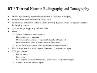
Production of neutrons at a spallation neutron source Generally the production of neutrons at a spallation source begins with a high-powered proton accelerator. The accelerator may consist of a linac only (as in the European Spallation Source) or a combination of linac and synchrotron (e.g. ISIS neutron source) or a cyclotron (e.g PSI) . As an example, the ISIS neutron source is based on some components of the former Nimrod synchrotron. Nimrod was uncompetitive for particle physics so it was replaced with a new synchrotron, initially using the original injectors, but which produces a highly intense pulsed beam of protons. Whereas Nimrod would produce around 2 µA at 7 GeV, ISIS produces 200 µA at 0.8 GeV. This is pulsed at the rate of 50 Hz, and this intense beam of protons is focused onto a target. Charlie Chong/ Fion Zhang
Experiments have been done with depleted uranium targets but although these produce the most intense neutron beams, they also have the shortest lives. Generally, therefore, tantalum or tungsten targets have been used. Spallation processes in the target produce the neutrons, initially at very high energies—a good fraction of the proton energy. These neutrons are then slowed in moderators filled with liquid hydrogen or liquid methane to the energies that are needed for the scattering instruments. Whilst protons can be focused since they have charge, chargeless neutrons cannot be, so in this arrangement the instruments are arranged around the moderators. Inertial confinement fusion has the potential to produce orders of magnitude more neutrons than spallation.[3] This could be useful for Neutron radiography which can be used to locate hydrogen atoms in structures, resolve atomic thermal motion and study collective excitations of photons more effectively than X-rays. Charlie Chong/ Fion Zhang
More R eading on ASTM E545 TUTOR IAL ON PR OPER IMAGE QUALITY INDICATOR USAGE Charlie Chong/ Fion Zhang
ASTM E545 TUTOR IAL ON PR OPER IMAGE QUALITY INDICATOR USAGE Neutron radiography is a non-destructive testing method similar to the more familiar x-ray, but which uses neutrons for a radiation source to expose the film. Because of the important differences in neutron radiography from X-Ray, a different kind of penetrameter is needed. The ASTM document E545 describes a pair of image quality indicators that have been accepted internationally as a standard for neutron radiography. The Beam Purity Indicator BPI measures the beam content of the source, whether from a reactor, an isotopic source, or an accelerator (or spallation neutron source). It is constructed of four simple materials so that the image of the BPI on the film can give both a quantitative analysis from measurements using a densitometer, and a qualitative analysis using the human eye for a quick visual check. Charlie Chong/ Fion Zhang
Figure 17.1: Picture and drawing of Beam Purity Indicator Charlie Chong/ Fion Zhang
Neutron images of the ASTM standards: (a) the Sensitivity Indicator and (b) its neutron image; (c) the Beam Purity Indicator (BPI) and (d) its neutron image. https://nars.osu.edu/ Charlie Chong/ Fion Zhang
Visible light photo and neutron image of four different scintillators https://nars.osu.edu/ Charlie Chong/ Fion Zhang
The Sensitivity Indicator is a more complex device, consisting of four steps of a plastic material, with holes and gaps built in to examine the resolution available. Its values are based on the film reader’s ability to see the smallest size hole or gap that can be resolved by the reader. four steps Charlie Chong/ Fion Zhang
SI - Sensitivity Indicator Charlie Chong/ Fion Zhang
E 2023 Shim Thickness Hole Diameter A 0.005 B 0.010 C 0.020 D 0.010 0.005 0.010 0.020 0.010 Charlie Chong/ Fion Zhang
E 545 DBFilm densities measured through the images of the boron nitride disks. DLFilm densities measured through the images of the lead disks. DHFilm density measured at the center of the hole in the BPI. DTFilm density measured through the image of the polytetrafluoroethylene. ∆DLDifference between the DL values. ∆DBDifference between the two DB values. Charlie Chong/ Fion Zhang
Figure 17.3: Photo of Beam Purity Indicator (left) and Sensitivity Indicator Charlie Chong/ Fion Zhang
Together this pair of image quality indicators can give the reader a basis for evaluating both the facility at which the film was created, and the resolution of the film itself. Details of construction of these devices can be found in ASTM E2003 and ASTM E2023. Charlie Chong/ Fion Zhang
Figure 17.4: Correct placement of Indicators in part holder Charlie Chong/ Fion Zhang
The BPI and SI should be placed no less than one inch from any edge of the film to avoid the edge effects of captured gamma from the conversion screen. The cadmium rods should be oriented such that their longitudinal axis is perpendicular to the nearest edge of the film, or edge effects will negate or exaggerate the differences between the disks. Correct placement: The BPI and SI should be placed no less than one inch from any edge of the film The cadmium rods should be oriented such that their longitudinal axis is perpendicular to the nearest edge of the film Pb cadmium rods BN one inch Diagnostic length film Charlie Chong/ Fion Zhang
Figure 17.5: Incorrect placement of indicators in part holder (three examples) Correct Charlie Chong/ Fion Zhang
Figure 17.4: Correct placement of Indicators in part holder Charlie Chong/ Fion Zhang
∆DB Scattered neutrons are indicated by a simple “reverse collimation” technique. The boron nitride disk adjacent to the cassette is assumed to absorb all thermal neutrons whether primary or scattered. The boron nitride disk that is 6 mm away from the cassette will remove all primary thermal neutrons but permit scattered neutrons to interact with the conversion screen within the boron nitride image area. Low angle scattered neutrons, outside a cone of approximately 33 degrees included angle, will be effective in degrading the contrast, since they have the effect of adding to the background density without providing any meaningful information. An analysis of the difference in density between the two boron disks will give the percentage of neutrons that are scattered in the beam. remove all primary thermal neutrons but permit scattered neutrons to interact with the conversion screen within the boron nitride image area. BN BN 6 mm absorb all thermal neutrons whether primary or scattered Charlie Chong/ Fion Zhang
An analysis of the difference in density between the two boron disks will give the percentage of neutrons that are scattered in the beam. ∆DBDifference between the two DB values. Calculate the effective scattered neutron content, S, as follows: Charlie Chong/ Fion Zhang
∆DL Similarly, the lead disk that is against the cassette will absorb all gamma photons while the disk that is 6 mm away from the cassette will allow them to darken the film. An analysis of the difference between the two lead disks will give the percentage of gamma that is in the beam, and low energy gamma is the most detrimental factor in neutron radiography. The relative thicknesses of the lead and the teflon are chosen so that the neutron attenuation for both is the same at those thicknesses. Calculate the effective gamma content, g, as follows: (DLlighter than DT) Calculate the effective pair production content, P, as follows: Charlie Chong/ Fion Zhang
the lead disk that is against the cassette will absorb all gamma photons while the disk that is 6 mm away from the cassette will allow them to darken the film. Pb disk that is 6 mm away from the cassette will allow scattered gamma ray to darken the film Pb 6 mm lead disk that is against the cassette will absorb all gamma photons Charlie Chong/ Fion Zhang
The cadmium wires should show about the same degree of sharpness at 5/16” apart. A significant difference between them indicates that the L/D ratio is likely too low for general inspection. (<35) Without using a densitometer, a radiographer can now analyze the BPI qualitatively. If there is a significant difference in the density of the two boron disks, the beam has many scattered neutrons. The lead disks should be approximately the same density as the Teflon block. ■ If the lead disks are visibly lighter than the Teflon block, there is a high gamma content. ■ If the lead disks are darker than the Teflon block, the beam has a high pair production content. Charlie Chong/ Fion Zhang
Low Gamma Content γ γ Pb γ γ Charlie Chong/ Fion Zhang
High Gamma Content γ γ Pb γ γ Charlie Chong/ Fion Zhang
High Pair Production γ γ Pb e-, e+ γ Charlie Chong/ Fion Zhang
Figure 17.6: Film image of Beam Purity Indicator Charlie Chong/ Fion Zhang
Visually, the radiographer can quickly determine if the beam contains significantly detrimental elements: scattered neutrons, gamma content, pair production, or low L/D ratio. Any of these observations indicates the need for further image analysis and subsequent determination of the usefulness of the radiograph for that particular inspection. Charlie Chong/ Fion Zhang
A densitometer that reads the amount of light transmitted through a film can also be used to obtain quantitative information. In this model, high-intensity light is generated in the bottom of the unit and allowed to escape through an aperture to the detector in the top, where it is read and reported logarithmically. Zero is 100% transmission of light, 1 is 10% transmission, etc. Figure 17.7: Light transmission densitometer D = log (Io/I) Charlie Chong/ Fion Zhang
The densitometer should be calibrated before use with a step-wedge calibrated to a national standard. Charlie Chong/ Fion Zhang
There are six density measurements to be taken from the image of the BPI. The order is not important, as it is the highest, lowest, or difference between the measurements that will determine the results. Use the densitometer to measure the density of the image of each boron disk, and each lead disk. The lead disks can be difficult to see in the densitometer, so use crosshairs to bisect the opposite corners and find the proper position for the densitometer. Figure 17.9: Measuring density of boron disk with densitometer Charlie Chong/ Fion Zhang
E 545 DBFilm densities measured through the images of the boron nitride disks. DLFilm densities measured through the images of the lead disks. DHFilm density measured at the center of the hole in the BPI. DTFilm density measured through the image of the polytetrafluoroethylene. ∆DLDifference between the DL values. ∆DBDifference between the two DB values. Charlie Chong/ Fion Zhang
Use the densitometer to measure the density of the image of the teflon block. A good place to do this is midway between the lead disks. Then do the same for the center hole. Record all six measurements. Charlie Chong/ Fion Zhang
Consult a copy of ASTM document E545. The formulas are printed in paragraph 10. To calculate the effective thermal neutron content, add the value of the higher of the two boron disks to the difference between the two lead values. Subtract this value from the hole, then divide by the value for the hole. Multiply by 100 to make it into a percentage. To calculate the effective scattered neutron content, divide the difference between the boron disks by the value for the hole, then multiply this quantity by 100. Charlie Chong/ Fion Zhang
To calculate the effective gamma content, subtract the lowest of the two lead values from the value for the teflon block, divide by the value for the hole, and multiply by 100. To calculate the effective pair production content, divide the difference between the lead values by the value for the hole, then multiply by 100. These results can then be compared to the figures in Table 4 of E545 to categorize the quality of the radiograph. Charlie Chong/ Fion Zhang
TABLE 4 Neutron Radiographic Categories NOTE 1—It should be recognized that these categories favor contrast factors because the sensitivity indicators do not permit accurate determination of sharpness alone. It may, therefore, be advantageous to use a lower number category when sharpness is a more important factor than contrast. Charlie Chong/ Fion Zhang
For example, a neutron radiograph that has a BPI on it that yields a thermal neutron content of 62%, a scatter content of 5%, a gamma content of 3%, and a pair production of 0.5% would qualify as a Category II radiograph. NC = 62% S = 5% g =3% P =0.5% Category II radiograph A neutron radiograph that yields a neutron content of 67%, a scatter content of 4%, a gamma content of 4%, and a pair production of 1% would also only qualify as a Category II radiograph because the gamma content did not meet Category I requirements. NC = 67% S = 4% g =4% P =1% Category II radiograph Charlie Chong/ Fion Zhang