Download
1 / 113
1.23k likes | 1.45k Vues
Undesrtanding ASTM E2261-Examination of Welds Using ACFM

E N D
Electromagnetic Testing Understanding ASTME2261.12 Examination of W elds Using the ACFM My ASNT Level III Pre-Exam Preparatory My Self Study Notes 6th August 2015 Charlie Chong/ Fion Zhang
Petrochemical Applications Charlie Chong/ Fion Zhang
Petrochemical Applications Charlie Chong/ Fion Zhang
Petrochemical Applications Charlie Chong/ Fion Zhang
Petrochemical Applications Charlie Chong/ Fion Zhang
Petrochemical Applications Charlie Chong/ Fion Zhang
Petrochemical Applications Charlie Chong/ Fion Zhang
Petrochemical Applications Charlie Chong/ Fion Zhang
Petrochemical Applications Charlie Chong/ Fion Zhang
Petrochemical Applications Charlie Chong/ Fion Zhang
Petrochemical Applications Charlie Chong/ Fion Zhang
Petrochemical Applications Charlie Chong/ Fion Zhang http://www.nbcnews.com/storyline/ukraine-crisis/chemical-plant-near-donetsk-eastern-ukraine-hit-explosion-n302821
Greek Alphabet Charlie Chong/ Fion Zhang
Charlie Chong/ Fion Zhang http://greekhouseoffonts.com/
Fion Zhang at Shanghai 6th August 2015 http://meilishouxihu.blog.163.com/ Charlie Chong/ Fion Zhang
IVONA TTS Capable. Charlie Chong/ Fion Zhang http://www.ivona.com/en/
My Mangosteen Charlie Chong/ Fion Zhang
qqqqqq Charlie Chong/ Fion Zhang NASA Nondestructive Testing Eddy Current Equipments Methods & Applications Volume-2
Standard Practice for Examination of W elds Using the Alternating Current Field Measurement Technique E2261-12 Charlie Chong/ Fion Zhang
1. Scope 1.1 This practice describes procedures to be followed during alternating current field measurement examination of welds for baseline (new fabrication?) and service induced surface breaking discontinuities. 1.2 This practice is intended for use on welds in any metallic material (ferrous & non-ferrous). 1.3 This practice does not establish weld acceptance criteria. 1.4 Units—The values stated in either inch-pound units or SI units are to be regarded separately as standard. The values stated in each system might not be exact equivalents; therefore, each system shall be used independently of the other. Combining values from the two systems may result in nonconformance with the standard. Charlie Chong/ Fion Zhang
1.5 This standard does not purport to address all of the safety concerns, if any, associated with its use. It is the responsibility of the user of this standard to establish appropriate safety and health practices and determine the applicability of regulatory limitations prior to use. Charlie Chong/ Fion Zhang
1.5 This standard does not purport to address all of the safety concerns, if any, associated with its use. It is the responsibility of the user of this standard to establish appropriate safety and health practices and determine the applicability of regulatory limitations prior to use. Charlie Chong/ Fion Zhang
2. Referenced Documents 2.1 ASTM Standards: • E543 Specification for Agencies Performing Nondestructive Testing • E1316 Terminology for Nondestructive Examinations 2.2 ASNT Standard: • SNT-TC-1A Personnel Qualification and Certification in Nondestructive Testing • ANSI/ASNT-CP-189 Standard for Qualification and Certification of Nondestructive Testing Personnel Charlie Chong/ Fion Zhang
3. Terminology 3.1 Definitions—For definitions of terms relating to this practice refer to Terminology E1316, Section A, Common NDT terms, and Section C, Electromagnetic testing. The following definitions are specific to the alternating current field measurement technique: 3.2 Definitions: 3.2.1 exciter—a device that generates a time varying electromagnetic field, usually a coil energized with alternating current (AC); also known as a transmitter. (coil magnetic field → induces an uniform AC magnetic field on mtls surface parallel to weld → This, in turn, causes alternating current to flow across the weld) Keywords: time varying electromagnetic field Charlie Chong/ Fion Zhang
Discussion Subject: “3.2.3 uniform field—as applied to nondestructive testing with magnetic fields, the area of uniform magnetic field over the surface of the material under examination produced by a parallel induced alternating current, which has been passed through the weld and is observable beyond the direct coupling of the exciting coil.” Question: How the parallel induced alternating current on the surface of the material first induced? (coil magnetic field → induces an uniform AC magnetic field on mtls surface parallel to weld → This, in turn, causes alternating current to flow across the weld → Any surface breaking discontinuities within a short distance of either side of the scan line at this location will interrupt or disturb the flow of the alternating current. ) Charlie Chong/ Fion Zhang
3.2.2 detector—one or more coils or elements used to sense or measure a magnetic field; also known as a receiver. 3.2.3 uniform field—as applied to nondestructive testing with magnetic fields, the area of uniform magnetic field over the surface of the material under examination produced by a parallel induced alternating current, which has been passed through the weld and is observable beyond the direct coupling of the exciting coil. Charlie Chong/ Fion Zhang
3.3 Definitions of Terms Specific to This Standard: 3.3.1 alternating current field measurement system—the electronic instrumentation, software, probes, and all associated components and cables required for performing weld examination using the alternating current field measurement technique. 3.3.2 operational reference standard—a reference standard with specified artificial slots, used to confirm the operation of the system. 3.3.3 Bx—the x component of the magnetic field, parallel to the weld toe, the magnitude of which is proportional to the current density set up by the electric field. (ФBx∝ H) or (Bx ∝ H?) Bx By Charlie Chong/ Fion Zhang
3.3.4 Bz—the z component of the magnetic field normal to the inspected base metal/heat affected zone surface, the magnitude of which is proportional to the lateral deflection of the induced currents in the plane of that surface. 3.3.5 X-Y Plot—an X-Y graph with two orthogonal components of magnetic field plotted against each other. (Bx & Bz) 3.3.6 time base plots—these plot the relationship between Bx or Bz values with time. (?) [is Bx’s x-axis representing time (distance)?] 3.3.7 surface plot—for use with array probes. This type of plot has one component of the magnetic field plotted over an area, typically as a color contour plot or 3-D wire frame plot. (topographic 3D plot?) 3.3.8 data sample rate—the rate at which data is digitized for display and recording, in data points per second. Charlie Chong/ Fion Zhang
3.3.6 time base plots—these plot the relationship between Bx or Bz values with time. (?) [is Bx’s x-axis representing time (distance)?] time base ? Charlie Chong/ Fion Zhang
3.3.9 configuration data—standardization data and instrumentation settings for a particular probe stored in a computer file. 3.3.10 twin fields—magnetic fields generated in two orthogonal directions by use of two exciters NOTE 1- different equipment manufacturers may use slightly different terminology. Reference should be made to the equipment manufacturer’s documentation for clarification. Charlie Chong/ Fion Zhang
4. Summary of Practice 4.1 In a basic alternating current field measurement system, a small probe is moved along the toe of a weld. The probe contains an exciter coil, which induces an AC magnetic field in the material surface aligned to the direction of the weld. This, in turn, causes alternating current to flow across the weld. The depth of penetration of this current varies with material type and frequency but is typically 0.004 in. [0.1 mm] deep in magnetic materials and 0.08 - 0.3 in. [2 - 7 mm] deep in non-ferrous materials. (coil magnetic field → induces an uniform AC magnetic field on mtls. surface parallel to weld → This, in turn, causes alternating current to flow across the weld → Any surface breaking discontinuities within a short distance of either side of the scan line at this location will interrupt or disturb the flow of the alternating current. ) Charlie Chong/ Fion Zhang
Any surface breaking discontinuities within a short distance of either side of the scan line at this location will interrupt or disturb the flow of the alternating current. The maximum distance from the scan line to a target discontinuity, potentially detectable at a specified probability of detection, is determined by the probe assembly size, but is typically 0.4 in [10 mm]. Measurement of the absolute quantities of the two major components of the surface magnetic fields (Bx and Bz) determines the severity of the disturbance (see Fig. 1) and thus the severity of the discontinuity. Comment: interrupt or disturb the flow of the alternating current is the basis of detection Charlie Chong/ Fion Zhang
FIG. 1 Example Bx and Bz Traces as a Probe Passes Over a Crack (The orientation of the traces may differ depending upon the instrumentation.) Charlie Chong/ Fion Zhang
Discontinuity sizes, such as crack length and depth, can be estimated from key points selected from the Bx and Bz traces along with the standardization data and instrument settings from each individual probe. This discontinuity sizing can be performed automatically using system software. Discontinuities essentially perpendicular to the weld may be detected (in ferritic metals only) by the flux leakage effect. However confirmation of such transverse discontinuities (and detection of the same in non-ferritic metals) requires scans with the induced magnetic field perpendicular to the direction of the weld. alternating current Charlie Chong/ Fion Zhang
4.2 Configuration data is loaded at the start of the examination. System sensitivity and operation is verified using an operation reference standard. System operation is checked and recorded prior to and at regular intervals during the examination. Note that when a unidirectional input current is used, any decay in strength of the input field with probe lift-off or thin coating is relatively small so that variations of output signal (as may be associated with a discontinuity) are reduced. If a thick coating is present, then the discontinuity size estimation must compensate for the coating thickness. The coating thickness requiring compensation is probe dependent. This can be accomplished using discontinuity-sizing tables in the system software and an operator-entered coating thickness or automatically if the equipment measures the coating thickness or stand-off distance during the scanning process. Using the wrong coating thickness would have a negative effect on depth sizing accuracy if the coating thickness discrepancy is too large. Data is recorded in a manner that allows archiving and subsequent recall for each weld location. Evaluation of examination results may be conducted at the time of examination or at a later date. The examiner generates an examination report detailing complete results of the examination. Charlie Chong/ Fion Zhang
Coating Thickness & Lift-off Compensation: This can be accomplished using discontinuity-sizing tables in the system software and an operator-entered coating thickness or automatically if the equipment measures the coating thickness or stand-off distance during the scanning process. Charlie Chong/ Fion Zhang
5. Significance and Use 5.1 The purpose of the alternating current field measurement method is to evaluate welds for surface breaking discontinuities such as fabrication and fatigue cracks. The examination results may then be used by qualified organizations to assess weld service life or other engineering characteristics (beyond the scope of this practice). This practice is not intended for the examination of welds for non-surface breaking discontinuities. Keywords: This practice is not intended for the examination of welds for non-surface breaking discontinuities. Charlie Chong/ Fion Zhang
6. Basis of Application 6.1 Personnel Qualification: 6.1.1 If specified in the contractual agreement, personnel performing examinations to this practice shall be qualified in accordance with a nationally or internationally recognized NDT personnel qualification practice or standard such as ANSI/ASNT-CP-189 or SNT-TC-1A or a similar document and certified by the employer or certifying agent, as applicable. The practice or standard used and its applicable revision shall be identified in the contractual agreement between the using parties. 6.2 Qualification of Nondestructive Evaluation Agencies—if specified in the contractual agreement, NDT agencies shall be qualified and evaluated as described in Practice E543, with reference to sections on electromagnetic examination. The applicable edition of Practice E543 shall be specified in the contractual agreement. Charlie Chong/ Fion Zhang
7. Job Scope and Requirements 7.1 The following items may require agreement by the examining party and their client and should be specified in the purchase document or elsewhere: 7.1.1 Location and type of welded component to be examined, design specifications, degradation history, previous nondestructive examination results, maintenance history, process conditions, and specific types of discontinuities that are required to be detected, if known. 7.1.2 The maximum window of opportunity for work. (Detection of small discontinuities may require a slower probe scan speed, or cleaning of surface, or both, which will affect productivity.) 7.1.3 Size, material grade and type, and configuration of welds to be examined. If required by type of equipment chosen, thickness of coating and variation of coating thickness. 7.1.4 A weld numbering or identification system. Charlie Chong/ Fion Zhang
7.1.5 Extent of examination, for example: complete or partial coverage, which welds and to what length, whether straight sections only and the minimum surface curvature. 7.1.6 Means of access to welds, and areas where access may be restricted. 7.1.7 Type of alternating current field measurement instrument and probe; and description of operations referece standard used, including such details as dimensions and material. 7.1.8 Required operator qualifications and certification. 7.1.9 Required weld cleanliness. 7.1.10 Environmental conditions, equipment and preparations that are the responsibility of the client; common sources of noise that may interfere with the examination. Charlie Chong/ Fion Zhang
7.1.11 Complementary methods or techniques may be used to obtain additional information. 7.1.12 Acceptance criteria to be used in evaluating discontinuities. 7.1.13 Disposition of examination records and reference standards. 7.1.14 Format and outline contents of the examination report. Charlie Chong/ Fion Zhang
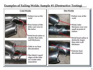
8. Interferences 8.1 This section describes items and conditions, which may compromise the alternating current field measurement technique. 8.2 Material Properties: 8.2.1 Although there are permeability differences in a ferromagnetic material between weld metal, heat affected zone and parent plate, the probe is normally scanned along a weld toe and so passes along a line of relatively constant permeability. If a probe is scanned across a weld then the permeability changes may produce indications, which could be similar to those from a discontinuity. Differentiation between a transverse discontinuity signal and the weld signal can be achieved by taking further scans parallel to the indication, or using an array probe. The signal from a discontinuity will die away quickly. If there is no significant change in indication amplitude at 0.8 in. [20 mm] distance from the weld then the indication is likely due to the permeability changes in the weld. Charlie Chong/ Fion Zhang
8.3 Magnetic State: 8.3.1 Demagnetization—It must be ensured that the surface being examined is in the non-magnetized state. Therefore the procedure followed with any previous magnetic technique deployed must include demagnetization of the surface. This is because areas of remnant magnetization, particularly where the leg of a magnetic particle examination yoke was sited, can produce loops in the X-Y plot, which may sometimes be confused with a discontinuity indication. Charlie Chong/ Fion Zhang
8.3.2 Grinding marks—magnetic permeability can also be affected by surface treatments such as grinding. These can cause localized areas of altered permeability across the line of scan direction. The extent and pressure of any grinding marks should always be reported by the probe operator, since these can give rise to strong indications in both Bx and Bz, which may be confused with a discontinuity indication. If a discontinuity is suspected in a region of grinding, further scans should be taken parallel but away from the weld toe and perpendicular across the region of grinding. The indication from a linear discontinuity will die away quickly away from the location of the discontinuity so that the scan away from the weld toe will be flatter. If there is no significant change in indication amplitude at 0.80 in. [20 mm] distance from the weld then the indication is likely due to the effect of the grinding. The indication from a region of grinding will be the same for the perpendicular scan. Charlie Chong/ Fion Zhang
8.4 Residual stress, with accompanying permeability variations, may be present with effects similar to those due to grinding, but are much smaller. 8.5 Seam Welds: 8.5.1 Seam welds running across the line of scanning also produce strong indications in the Bx and Bz, which can sometimes be confused, with a discontinuity indication. The same procedure is used as for grinding marks with further scans being taken away from the affected area. If the indication remains constant then it will not have been produced by a linear discontinuity. 8.6 Ferromagnetic and Conductive Objects: 8.6.1 Problems may arise because of objects near the weld that are ferromagnetic or conductive which may reduce the sensitivity and accuracy of discontinuity characterization when they are in the immediate vicinity of the weld. Charlie Chong/ Fion Zhang
8.7 Neighboring Welds: 8.7.1 In areas where welds cross each other, there are indications, which may be mistaken for discontinuities. (See 8.5.) 8.8 Weld Geometry: 8.8.1 When a probe scans into a tight angle between two surfaces the Bx indication value will increase with little change in the Bz value. In the representative plot of Fig. 2, this appears as a rise in the X-Y plot. If the equipment is capable of measuring lift-off, the lift-off will also change. Charlie Chong/ Fion Zhang
FIG. 2 Example X-Y Plot Produced by Plotting the Bx (vertical) and Bz (horizontal) Together (The orientation of the plot may differ depending upon the instrumentation.) Bx Bz Charlie Chong/ Fion Zhang
8.9 Crack Geometry Effects: 8.9.1 A discontinuity at an angle to the scan—a discontinuity at an angle to the scan will reduce either the peak or the trough of the Bz as the sensor probe only passes through the edge of one end of the discontinuity. This produces an asymmetric X-Y plot. Additional scans may be made along the weld or parent plate to determine the position of the other end of the discontinuity. 8.9.2 A discontinuity at an angle to the surface—the effect of a discontinuity at a non-vertical angle to the probe is generally to reduce the value of the Bz signal. The value of the Bx signal will not be reduced. This has the effect of reducing the width of the X-Y plot in the representative plot of Fig. 2. 8.9.3 Line contact or multiple discontinuities—when contacts occur across a discontinuity then minor loops occur within the main X-Y plot loop produced by the discontinuity. If more than one discontinuity occurs in the scan then there will be a number of loops returning to the background. Charlie Chong/ Fion Zhang