Download
1 / 48
480 likes | 630 Vues
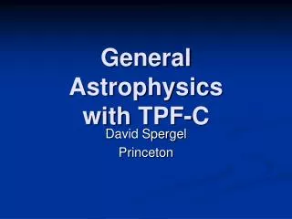
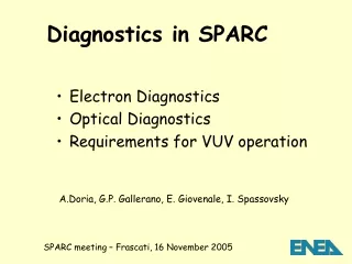
TPF-C Optical Requirements . Stuart Shaklan TPF-C Architect Jet Propulsion Laboratory, California Institute of Technology with Contributions from Luis Marchen, Oliver Lay, Joseph Green, Dan Ceperly, Dan Hoppe, R. Belikov, J. Kasdin, and R. Vanderbei TPF-C Coronagraph Workshop

E N D
TPF-C Optical Requirements Stuart Shaklan TPF-C Architect Jet Propulsion Laboratory, California Institute of Technology with Contributions from Luis Marchen, Oliver Lay, Joseph Green, Dan Ceperly, Dan Hoppe, R. Belikov, J. Kasdin, and R. Vanderbei TPF-C Coronagraph Workshop September 28, 2006
Overview • Flowdown of science requirements to engineering requirements • Meeting the requirements: TPF-C FB-1 Error Budget • Optical surface requirements • Related to wave front control system and bandwidth • Effect of uncontrolled spatial frequencies (frequency folding) • Related to finite size of the star • Image plane mask surface roughness requirements • Thermal/Dynamics requirements • Sensitivity of different coronagraphs to low-order aberrations • System requirements
High-Level Requirements • SCIENCE: Detect 30 potentially habitable planets assuming hearth =1. • Also measure orbital semi-major axis, perform spectro-photometry, detect photons from 0.5 – 1.1 um, perform spectroscopy. • Ongoing MISSION STUDIES have been used to derive engineering requirements from science requirements. • For the Flight Baseline 1 (FB-1) study, emphasis was first placed on the detection requirement. • ENGINEERING: The Mission Studies reveal that the detection requirement is satisfied with IWA = ~65 mas and SNR=5 at Dmag = 25.5 (Contrast = 6.3e-11), using a100 nm wide channel. • Orbit, spectro-photometry, and spectroscopy requirements will likely drive us to a deeper contrast requirement. • FLOWDOWN: • Control Scattered light to below Zodi + ExoZodi, ~ 1e-10 • Measure, estimate, or subtract speckles to 5x below Dmag = 25.5 or 1.2e-11 • Work at 4 l/D with D=8 m (equiv to 2 l/D for D=4 m).
CONTRAST CONTRAST STABILITY STATIC BUDGET DYNAMIC BUDGET Speckle Floor, Stability Contrast = Is + <Id> Stability = sqrt(2Is<Id> + <Id2>) Is = Static Contrast Wave Front Sensing Wave Front Control Gravity Sag Prediction Print Through Coating Uniformity Polarization Mask Transmission Stray Light Micrometeoroids Contamination Id = Dynamic Contrast Pointing Stability Thermal and Jitter Motion of optics Beam Walk Aberrations Bending of optics
TPF-C Baseline Error Budget Static vs. Dynamic Speckle variability exceeds requirement in this region.
- Phase and amplitude variations across the pupil Fp(l) - Phase and amplitude dependence of DM correction Fc(l) Fp(l) comes from unpropagated (‘direct’) terms, and propagated energy. Both must be considered. If Fp(l)≠Fc(l) Contrast Residual Contrast lo lo-Dl/2 lo+Dl/2 Where do TPF-C surface requirements come from? Axiom: Given a pair of ideal DMs, a stable telescope, and monochromatic light, all energy in the dark hole can be completely removed. - Independent of the wave front quality of the optics. What happens in broad-band light?
Michelson Wave Front Control y Incoming Light P Pupil Conjugate DM D q z DM a=4ps/l Phase control: 1/l Ampl. Control: 1/l2 To Coronagraph Collimated light reflects from an optic having a periodic surface deformation of r.m.s. height s. The light propagates a distance z to the pupil (or conjugate plane) where the wave front correction system is located. The system shown is a dual deformable mirror (DM) corrector in a Michelson configuration. The DMs control both amplitude and phase.
Sequential WFC Incoming Light D DMp zDM DMnp Pupil Image To Coronagraph Phase control: 1/l Ampl. Control: l independent Two DMs are separated by distance zDM. One is at the pupil. The pupil DM controls phase. The non-pupil DM adjusts its phase, which propagates to the pupil and becomes wavelength-independent amplitude.
Visible Nuller DM element tip-tilt Output power q SM Fiber q Coupling vs. tilt llong I Coupling vs. frequency no coupling DI(no) DI(n) lshort q The factor of 2 scaling with frequency arises from the combined scaling of both the image and fiber mode with frequency. n coupling Phase control: 1/l Ampl. Control: 1/2l A segmented-DM is matched to a lenslet array that couples light into a single-mode fiber optic. DM-element tilt adjusts the coupling efficiency, resulting in a change in the output light level.
Image Plane Pupil Plane a D z d D/N r = reflectivity Diffracted component phase delay is Propagation Kernel
SM PM M4 Cyl1 M3 CDM and PM DMcol Cyl1 DMcol M4 Cyl2 SM Cyl2 M3 TPF-C Layout Image-space images of the optics Final beam is collimated at the exit pupil. All optics appear to have the same diameter as seen from the exit pupil.
Surface Height Requirementsfor R=6.3 and C = 1e-12 per optic Surface Requirement Michelson and Visible Nuller Surface Requirement Sequential Secondary DMcol Secondary DMcol DMcol Dl=50 nm M4 DMcol Dl=50 nm DMcol Dl=200 nm M4 EUV EUV DMcol Dl=200 nm
Reflectivity Uniformity Requirementfor R=6.3, C=1e-12 Limited by ampl.-to- phase prop. Control limit for 30 nm piston, DM is 3 m from pupil Limited by direct reflectivity. Michelson and Visible Nuller Requirement We believe that the state-of-the-art in large optics coatings is about 0.5% r.m.s., with a 1/f3 PSD. This leads to ~ 1e-11 contrast at 4 cycles/aperture (worse at 2 cycles/aperture).
Finite Size Source DM compensation is sheared for an off-axis element of the target. Incoming Light D DMp zDM DMnp Pupil Image To Coronagraph Two DMs are separated by distance zDM. One is at the pupil. The pupil DM controls phase. The non-pupil DM adjusts its phase, which propagates to the pupil and becomes wavelength-independent amplitude.
Contrast Due to Finite Size Source C = Contrast s = r.m.s. wavefront (radians) or r.m.s. (reflectivity/2) dx = beam shear N = cycles/aperture D = beam diameter a = Source radius z = effective distance of optic from pupil Dp= pupil diameter Db= beam diameter
Surface Height Requirementsfor Finite Size Star (1.7 mas diam.), C = 1e-12 per optic Secondary Secondary M4 M4 Surface Requirement Michelson and Visible Nuller Surface Requirement Sequential Secondary DMcol Secondary DMcol DMcol Dl=50 nm M4 DMcol Dl=50 nm DMcol Dl=200 nm M4 EUV EUV DMcol Dl=200 nm
PM & SM Requirement on PM & SM for sequential controller, with znp=3 m from the pupil Reflectivity Uniformity Requirementfor Finite Size Star (1.7 mas diam.), C = 1e-12 per optic Control limit for 30 nm piston, DM is 3 m from pupil Michelson and Visible Nuller Requirement
Preferred DM Configuration Collim. M1 CDM M2 DMnp,1 DMp DMnp,2 Cass. Focus 1 f1=2.5 f2=2.5 1 zDM=3 zDM=3 3-DM fully redundant system. This diagram depicts an unfolded layout that provides for 2 non-pupil DMs placed zDM=3 m from the pupil DMp. A unity magnification telescope images the coarse DM pupil plane CDM to DMp (dashed line). The design provides 1 m between CDM-M1 and M2-DMnp,1 to fold the beams at a shallow angle.
LESSON 1 • Use a sequential wave front controller. • Relaxes optical surface requirements • Increases the useful size of the dark hole • Allows a wider optical bandwidth • Relaxes coating requirements on PM and SM to within state-of-the-art • Provides redundancy • A Michelson controller, and fiber spatial-filter amplitude controller make broad-band amplitude control very challenging. • Pushes Silver coating beyond state-of-the-art • Is Aluminum coating uniformity sufficient? • Aluminum is desired on PM, SM, and M3 to enable general astrophysics.
Phase in the pupil: Mixing of spatial frequencies. We are concerned with |m-n|<N /2. These pure-amplitude terms . Field in the pupil: Ideal diffraction, removed by coronagraph Scatter removed by DM, up to N cycles across the dark hole Frequency Folding: Uncontrolled High Spatial Frequencies Appear in the Dark Hole The previous charts addressed controllable spatial frequencies – those below the DM Nyquist frequency. Give’on has shown that frequency folding terms scatter light into the dark hole.
The sequential controller has l-independent amplitude control. The resulting contrast in the dark hole is: Frequency Folding Residual The Michelson controller has 1/l2 amplitude dependence and completely removes the light. The Visible Nuller fiber array does not pass spatial frequencies above N/2. The frequency folding problem is eliminated.
Frequency Folding Contrastfor R=6.3, Sequential DMs (96 x 96)
LESSON 2 • Uncontrolled high-spatial frequencies look manageable. • Existing optics lead to acceptable frequency folding • What happens when we light-weight the PM??? • Requires large format DM • Becomes an issue for bandwidth >> 100 nm
Image Plane Mask errors Static contrast Mask error Random Systematic Spatially random variations in mask transmission amp and phase Variations in mask transmission amp and phase that are correlated with mask pattern Unaberrated input field with mask errors
Gaussian error, monochromatic 550 nm • Unaberrated sombrero function E0 • Gaussian mask error DM at ~ 4l / D E field • E field error exiting mask = E0DM E field • Diffracted by Lyot stop • E0DM *L • Perfect DM correction (dotted line) E field Angular offset / rad
Gaussian error, broadband 550 nm + 510 nm • Two wavelengths to illustrate broadband case • Blue sombrero function is compressed E field • E field at mask exit is quite different at 510 nm E field • DM correction still perfect for 550 nm, but compressed for 510 nm • DM correction is completely inappropriate for 510 nm 510 nm error beforeDM correction 510 nm after DM ‘correction’ E field DM ‘correction’@ 510 nm 550 nm errorand correction Angular offset / rad
Dependence on error spatial scalefor a 100 nm bandpass 500-600 nm, evaluated at 4 l/D • Simple 1-D analysis used to predictcontrast in image plane from a grid ofrandom Gaussian mask errors • Light scattered from both verysmall features is blocked by Lyot stop • Large scale errors are effectively controlled over a broad band. Large • Most sensitive to scalescomparable to sidelobes ofsombrero function: Small
Mask error PSD requirement • Each component has different characteristic spatial scale • Each represents 10-11 contrast • Overall contrast can be suballocated to different scales to match actual PSD of mask errors Norequirement Period = 100 mm Period = 30 mm Overall surface r.m.s. ~ 1 A for scales 2 – 60 um. 91 pm rms (60 um scale size) 31 pm rms sum 24 pm rms (15 um scale size)) 27 pm rms 38 pm rms 50 pm rms (2 um scale size)
LESSON 3 • If you’re going to put a transmissive mask in the image plane, it should have <1 A rms for spatial scales up to 2 lF# • Due to inherent scaling of spatial frequency with wavelength in the image plane • A mask-leakage error looks like a planet – it does not scale with wavelength. • Calibrate by rotating the mask, but still requires 1 A rms to keep scattered light level near 1e-11.
Thermal/Dynamics Error Budget • Observing Scenario • Coronagraph sensitivity to Low-Order Aberrations • Control systems • Key Requirements
Scattered Light must be stable to ~ 1e-11 during this time Observing Scenario
Aberration Sensitivity 2Contrast Sensitivity Curves Coma, 3 l/D Focus, 3 l/D Evaluated at 4 l/D Coma, 4 l/D Coma, 4 l/D Focus, 4 l/D Focus, 4 l/D Linear dual-shear VNC aberration sensitivity and Lyot throughput are identical to a linear 4th order mask of the form T = 1-cos(x). Sensitivity is almost identical to 1-sinc2(x).
TILT FOCUS COMA ASTIG TREFOIL ASTI2 SPHERICAL Aberration Sensitivity 4Pupil Mapping Sensitivity Curves
COMA 10-8 Aberration Sensitivity 5Pupil Mapping Sensitivity Curves Pupil Mapping, 2 lambda/D BL4, VNC 4 lambda/D Pupil Mapping, 4 lambda/D Shaped Pupil, 4 lambda/D BL8, 4 lambda/D
Open-Loop Aberration Sensitivity Summary • The 8th-order null of a properly built BL8 provides orders-of-magnitude reduction to low-order aberrations. • Working at 4 l/D, the mask sensitivity to aberrations increases in order: • BL8, Shaped pupil, Pupil Mapping, BL4/VNC • BL4/VNC is 100 x more sensitive to aberrations than BL8 (C=1e-12) • OVCn behaves like 2nth null (OVC4 = 8th order null). Still studying the tradeoff between sensitivity and throughput. • Working at 3 l/D increases aberration sensitivity by an order of magnitude. • 3x tighter WF tolerance to work at 3 l/D with BL8 • Working at 2 l/D is harder yet – BL8 throughput too low, so must go to BL4/VNC, OVC2 or OVC4 (?), or pupil mapping. • This is 1000x more sensitive to aberration than BL8 at 4 l/D.
Thermal/Dynamic Error Budget • Low-order aberrations arise by • Thermal deformation and misalignment of optics • Jitter induced deformation and misalignment of optics • The BL8 mask at 4 lambda/D is quite insensitive to these. • BL4/VNC are the most sensitive • Beam Walk (shearing of spatial frequencies) is the same for all coronagraphs. • If planet light is transmitted at x lambda/D, then a spatial frequency of x cycles/aperture is also transmitted. • Beam walk is mitigated by • Control of optics positions: secondary mirror + FSM • Quality of optics • Beam walk drives the optical surface quality at a few cycles/aperture.
Control Systems • 3-tiered pointing control • Rigid body pointing using reaction wheels or Disturbance-Free Payload • Secondary mirror tip/tilt (~ 1 Hz) • Fine-guiding mirror (several Hz) • PM-SM Laser Metrology and Hexapod • Measures and compensates for thermal motion of secondary relative to primary.
Key Dynamics Requirements PM shape: (Thermal and Jitter) z4=z5=z6=z8=z10=0.4 nm z7=0.2 nm, z11=z12=5 pm Secondary: Thermal: x=65 nm, z=26 nm, tilt=30 nrad Jitter: 20x smaller z Laser metrology: L=25nm f/f=1x10-9 Mask centration: offset=0.3 mas amplitude=0.3mas Mask error = 5e-4 at 4 l/D Fold mirror 1: rms static surf =0.85nm Thermal: 10nrad, 100 nm Jitter: 10 nrad, 10 nm 4 mas rigid body pointing Figure 5. We identify the major engineering requirements to meet the dynamic error budget. Thermally induced translations lead to beam walk that is partially compensated by the secondary mirror. Jitter is partially compensated by the fine guiding mirror. Coronagraph optics motion: Thermal:10nrad, 100nm Jitter: 10 nrad, 10 nm
Changes from Baseline • Baseline design assumes BL8 mask. • Relatively insensitive to low-order aberrations. • Baseline observing scenario is: • Difference two images made at 30 deg LOS ‘dither’ positions • No DM reset for several hours during this time • If we switch to BL4, VNC (and to a lesser extent pupil mapping and shaped pupil), and if we keep the same observing scenario • We can NOT move secondary mirror to compensate tip-tilt because moving the secondary introduces significant low-order aberration • We must therefore maintain very strict pointing accuracy – sub milli-arcsec – on the telescope • We also tighten primary mirror bending stability by orders of magnitude. • Going to 2 lambda/D with pupil mapping requires even tighter tolerances.
LESSON 4 • Working at 2 or 3 l/D is much, much harder than 4 l/D. Breakthroughs in wave front control, optical surface quality, and a change in observing paradigm are needed. • Single-digit picometer wave front control for low-order aberrations • Sub-pm control of spherical aberration and higher order terms • Wave front control that is faster than the rigid body pointing errors • Or, require extremely tight rigid-body pointing • Hopefully we will hear some ideas on how to do this tonight and tomorrow.
Summary • Design Reference Mission modeling provides flow down of science requirements to engineering requirements. • Optical Surface Requirements • We have a good handle on surface height and reflectivity uniformity requirements through the system. • The requirements are imposed by • Wavelength-dependence of scatter vs. compensation • Finite size of the star • Thermal/Dynamic beam walk • High-spatial frequency errors on large mirrors appear to be acceptable for 100 nm bandwidth • Correction beyond ~ 25 cycles/aperture does not look feasible (but maybe can live with reduced performance at large working angles). • Image plane mask requirements • We have a good handle on the PSD of random mask transmission errors. • Superpolish surfaces (<1 Angstrom r.m.s.) are probably adequate. • Stability Requirements • Thermal and jitter requirements are well understood. • Modeling described in the FB-1 report and STDT report shows that the required stability can be achieved assuming an 8th-order band limited mask at 4 l/D. • Smaller IWA using masks that are more sensitive to aberrations requires a new approach to WFS/C, one that meets picometer stability requirements and 1e-11 calibration of speckles.
Disturbance Rigid Body Pointing Control PSD Models 4 mas Secondary 2ndry Beam Walk C-Matrix Dx CBW 0.4 mas Telescope Model MACOS FGM FGM Beam Walk C-Matrix Dx Contrast CBW Figure 2. Pointing control. The CEB assumes a nested pointing control system. Reaction wheels and/or a Disturbance Reduction System control rigid body motions to 4 mas (1 sigma). The telescope secondary mirror tips and tilts to compensate the 4 mas motion but has a residual due to bandwidth limitation of 0.4 mas. A fine guiding mirror in the SSS likewise compensates for the 0.4 mas motion leaving 0.04 mas uncompensated. 0.04 mas Telescope Telescope Beam Walk C-Matrix Dx CBW Pointing Control