Download
1 / 32
320 likes | 326 Vues
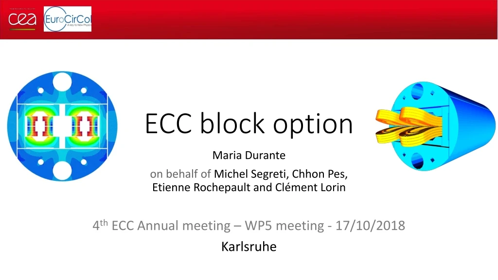
ECC block option. Maria Durante on behalf of Michel Segreti , Chhon Pes, Etienne Rochepault and C lément Lorin 4 th ECC Annual meeting – WP5 meeting - 17/10/2018 Karlsruhe. Overview. Design version v4ari250 : inter-beam 250 2D magnetic design Harmonics Persistent currents

E N D
ECC block option Maria Durante on behalf of Michel Segreti, Chhon Pes, Etienne Rochepault and Clément Lorin 4th ECC Annual meeting – WP5 meeting - 17/10/2018 Karlsruhe
Overview Design version v4ari250 : inter-beam 250 2D magnetic design Harmonics Persistent currents Random geometrical errors 3D magnetic design 2D mechanical design 3D mechanical design (ongoing) 4th ECC Annual meeting
v4ari250 : inter-beam 250 v4ari250 High field strand diameter: 1.1 mm (for procurement reason) Heat treatment dimensional change: +1% width ; +3% thickness Bore thickness: 1.9 mm including 0.5 mm thick ground insulation Inter-beam distance: 250 mm Yoke outer diameter: 616 mm Space for He cooling 2xDN106 + 4xDN32 20 mm SS-shell Coldmass outer diameter target : 800 mm 250 mm inter-beam 616 yoke outer diameter 72 mm Al shell + 20 mm SS shell 800 total outer diameter 4th ECC Annual meeting
2D magnetic design main parameters v4ari250 10 22 22 10 5 21 5 21 ** Area x 4578 dipoles x 14.3 m x 8.7 kg/m3 ** Estimated by ROXIE, but in fact > 14 % (14.67 %) 4th ECC Annual meeting
HF and LF Cables (unchanged since 2017) v4ari250 10 22 22 10 5 21 5 21 4th ECC Annual meeting
Harmonic content v4ari250 At Inom = 10176 A Without persistent current b2 max = 15 units at 3053 A 4th ECC Annual meeting
Persistent currents v4ari250 Nominal current = 10176 A Low field turning point (reset current) = 100 A Currentcycle:0 A 10176 A (first ramp up, pre-cycle) 100 A (first ramp down, pre-cycle) 10176 A (second ramp up) 100 A (second ramp down) Calculations at the reference radius = 16.67 mm (i.e. at 2/3 of the aperture radius) in the right aperture i.e. at x = 125 mm Injection at 3.3 TeV i.e. at 16 T x 3.3 / 50 = 1.056 T (corresponding to 531 A for the v4ari250 magnetic model) 4th ECC Annual meeting
Persistent currents v4ari250 b3 = -12.89 units at injection b5 = 2.70 units at injection b7 = -5.64 units at injection b9 = -2.40 units at injection b4 = 0.97 units at injection b2 = 9.40 units at injection
Random geometric errors v4ari250 • Modeling of random geometric errors withROXIE • CalculationswithOpera are ongoing Results for rms of 100 µm Results for rms of 50 µm 4th ECC Annual meeting
3D magnetic design - Assumptions Assumptions: Return ends – 1000 mm straight section Hardway bend : Rmin = 450 mm in upper layer (w = 12.6 mm) Strain 13.8 mm/m (HD2: 30.6 mm/m HD3: 12.4 mm/m Fresca2: 15.3 mm/m) Coil-to-aperture y-direction: 5 mm Double pancake end 5 mm 4th ECC Annual meeting
3D Magnetic Design – Options • Long: • Extension of coil ends • Compensation of the b3 in theends • Compact: • Coil ends to the shortest • Room in the spacers for internal joints • b3 compensated in the SS • Minimum conductor length Lstraight section = Liron 4th ECC Annual meeting
3D Magnetic Design – Options 3. 2. 1. Lss Lcoil • Baseline: • Short ends • Low harmonics • Margin (ΔBpeak > 0.6 T) Lmag Lcoil end 4th ECC Annual meeting
3D Magnetic Design main parameters v4ari250 At Inom = 10176 A b3 Peak field in straight part: 16.7 T (ROXIE 2D) 16.6 T (OPERA 3D) Peak field in ends: 15.8 T (OPERA 3D) Units Units b2 Z (mm) Z (mm) 4th ECC Annual meeting
2D Mechanical model - Bladder inflation ANSYS MODEL V4ari250with outer yoke Ø = 616 mm 72 mm thick Al shell 3 horizontal bladders: 1800 µm for 1600 µm 1 vertical bladder: 330 µm for 100 µm No 20 mm thick SS shell for bladder inflation peak von Mises stress in coil < 100 MPa 59 MPa 40 MPa ux uy 59 MPa 59 MPa 4th ECC Annual meeting
2D Mechanical model – Keys and SS shell ANSYS MODEL V4ari250with outer yoke Ø = 616 mm 72 mm thick Al shell + 20 mm thick SS shell 2 horizontal keys 412 µm + 1185 µm Vertical keys 100 µm ↓ Imposed displacement on SS shell bottom: -0.2 mm Contacts/symmetry: Bonded: inside the coils, with the poles Separation allowed with 0.2 friction: between the coils, with the structure ¼ of the structure ux = 0 4th ECC Annual meeting
Stress distribution - Coils Cold – 4.2 K 16 T Key + SS shell σX -147 MPa -180 MPa -185 MPa von Mises 4th ECC Annual meeting +136 MPa +165 MPa +167 MPa
σx at coil / pole interface LEFT RIGHT Only compression stress No tensile stress 4th ECC Annual meeting
Von Mises stress distribution – Ti Poles Cold – 4.2 K 16 T Key + SS shell von Mises 875 MPa 640 MPa 1110 MPa 4th ECC Annual meeting
Von Mises stress distribution – Y pusher Cold – 4.2 K 16 T Key + SS shell von Mises 420 MPa 60 MPa 624 MPa 4th ECC Annual meeting
Stress distribution – Iron Y-pad Cold – 4.2 K 16 T Key + SS shell von Mises 519 MPa 213 MPa 631 MPa Sigma I *σI < 380 MPa 4th ECC Annual meeting 168 MPa 92 MPa
Stress distribution – Iron X-pad Cold – 4.2 K 16 T Key + SS shell von Mises 475 MPa 324 MPa 488 MPa Sigma I *σI < 380 MPa 4th ECC Annual meeting 189 MPa 137 MPa
Stress distribution - Yoke Cold – 4.2 K 16 T Key + SS shell von Mises 707 MPa 550 MPa 759 MPa Sigma I *σI < 380 MPa 4th ECC Annual meeting 358 MPa 306 MPa
Azimuthal stress distribution – Al shell Cold – 4.2 K 16 T Key + SS shell σθ 280 MPa 165 MPa 299 MPa 4th ECC Annual meeting
Azimuthal stress distribution – SS Shell Cold – 4.2 K 16 T Key + SS shell σθ 227 MPa 266 MPa 248 MPa 4th ECC Annual meeting
3D Mechanical design (ongoing) Ansys 3D model • Contacts/symmetry: • Bonded: inside the coils, with the poles • Separation allowed with 0.2 friction: between the coils, with the structure • ¼ of the structure 4th ECC Annual meeting
3D Mechanical design - Next steps Comparisonbetween 2D and 3D @ z = 0 results Impact of the SS length on coil-ends results 1 m and 2 m SS models Axial stress 3D Mechanical design : End-shoe/end plate interference, x interferenceincrease, needed to keep end shoe and end plate in contact 4th ECC Annual meeting
Conclusion for the magnetic design • A 3D double aperture electromagnetic model has been developed by optimizing the field quality and the magnetic and physical lengths (coil ends as short as possible) • Persistent current is taken into account with ROXIE 2D • A random geometric errors analysis with ROXIE has been realized • Calculations results with Opera are foreseen soon • As the block coil is the same than for the v2ari194 model presented last year, we assume that Hotspot and Voltage to ground remain below the limit 4th ECC Annual meeting
Conclusion for the mechanical design • Investigation of a double aperture 2D mechanical design with 250 mm inter-beam distance, @ 16 T • Total outer diameter of 800 mm (SS shell outer diameter) • Bladder pressure of 59 MPa in operation • Peak stress in Nb3Sn coil below the limit • Peak stress in the horizontal iron components above the limit at warm (key contact with lateral yoke and horizontal pad) • Almost operational Ansys 3D model 4th ECC Annual meeting
Thanks for yourattention 4th ECC Annual meeting
Random geometric errors v4ari250 Inputs for ROXIE 2D for rms of 100 µm and 50 µm 4th ECC Annual meeting
Material properties (Davide 3rd FCC week) • Coil maximum stress • @ 4.2 K: 200 MPa • @ 300 K: 150 MPa *Ferromagneticiron @ 4.2 K stress < 380 MPa in tension (1st principal stress) 4th ECC Annual meeting
Synthesis of 2D mechanical designs v5ari204 v4ari250 Interbeam distance = 204 mm Øext iron yoke = 570 mm Total Øext = 744 mm 67 + 20 mm thick shells 2 x 720 µm Interbeam distance = 250 mm Øext iron yoke = 616 mm Total Øext = 800 mm 72 + 20 mm thick shells 412 µm + 1185 µm 4th ECC Annual meeting