Download
1 / 20

E N D
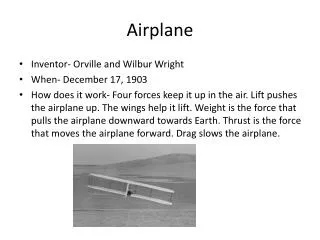
Airspeed The Airspeed Indicator measures the speed of the airplane as it goes through the air. On a day without any wind, the indicated airspeed would be the same as the speed of the airplane going over the ground. However if the plane is going into a headwind of 15 MPH at an indicated airspeed of 135 MPH, the ground speed would be 120 MPH. Likewise the plane had a 15 MPH tail wind, the ground speed would be 150 MPH. The instrument operates with Ram or impact air entering the pitot tube. It also uses static air pressure in the case as a reference for the ram air pressure. The impact air pushes on a diaphragm which moves the indicating needle on the instrument face. The instrument is color coded to alert the pilot to the various operating speeds of the aircraft.
Attitude Indicator The Attitude Indicator, or sometimes called the, Artificial Horizon, is a vacuum driven gyroscopic instrument. It relays information to the pilot as to the flight attitude of the plane, whether it is climbing, descending, or banking. The white line going across the face of the instrument represents the horizon, blue the sky, black, the ground. The power for the instrument comes from the suction through a closed system generated by a vacuum pump. The air flowing through the instrument case moves vanes attached the gyroscope, causing the gyroscope to spin and the instrument to operate.
Altimeter The Altimeter is an aneroid barometer which converts a barometric pressure reading measured in inches of mercury into an altitude measured in feet. It measures the altitude of the aircraft above sea level when the altimeter is set to the current barometric pressure setting. If the elevation of an airport is 670 feet above sea level, when set correctly, the altimeter should read 670 feet while the airplane is still on the ground. As the plane climbs the decreasing pressure of the static air relaxes a bellows in the instrument. When the bellows moves, a linkage connected to the hands of the instrument increases the indicated altitude. When the plane descends, the bellows expands due to the higher pressure, with a decrease in indicated altitude.
Turn Coordinator The Turn Coordinator is actually two instruments in one. The miniature airplane is an electrically driven gyroscope that initially measures the rate of roll of a bank. Once the bank is stabilized, the instrument measures rate of turn of a bank. The two white marks below the wingtips of the airplane are timing marks. When the wingtip is aligned with the either mark, depending on the direction of the bank, it will take 2 minutes to make a complete 360 degree turn. The black ball below the miniature airplane is in a fluid filled tube called and inclinometer. It is very much like a common carpenters level. The only power driving this portion of the instrument is centrifugal force acting on the airplane during a turn. When the ball stays in the middle during a bank, the turn is coordinated. If the ball falls to the side of the dipped wing during a turn, the plane is in a slipping turn. If the ball is opposite of the dipped wing, the plane is in a skidding turn.
Directional Gyro The Directional Gyro is another vacuum driven gyroscope. It looks much like a compass. A major difference it has with the compass is that it doesn’t rely on the earth’s magnetic field to operate. When the gyroscope is spinning it has a principle of remaining rigid in space. That is the spinning wheel will resist any change in position. The DG takes advantage of that principle. When an airplane is turning the gyroscope will resist moving with the turn. The energy used to resist the turn instead moves the compass card which will indicate the heading of the airplane. DG’s are used because they are not effected by magnetic disturbances or have turning errors inherent to the compass. They are susceptible to gyroscopic precession which are errors due to the mechanical friction imposed on the spinning gyroscope.
Vertical Speed Indicator The Vertical Speed Indicator measures the speed at which the plane climbs or descends. Like the altimeter, it measures the pressure changes of the static air. Where the altimeter traps the static air in the case to maintain the indicated altitude, the VSIallows the pressurized air in or out of the instrument at a controlled rate. The rate the air comes in or goes out of the instrument is translated into feet per minute. On the ground high static pressure is inside the instrument. As the plane climbs, the high pressure leaks out a calibrated hole in a bellows. As the bellows contracts, a linkage moves the indicator hand upward showing a climb. As the plane descends, the bellows expands by the intake of the higher static pressure. The indicating hands then show a descent. The rate the air moves in or out of the instrument determines how much the needle moves.
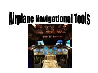
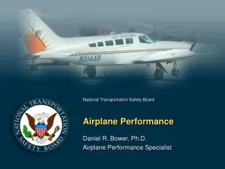
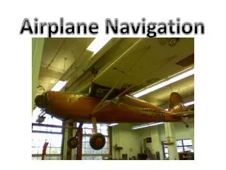
Cockpit Displays New Plane Historic Plane
Newer Plane Newer Plane
VOR Visual Omni Range is and instrument that receives high frequency radio signals from a transmitting station.
DME Distance Measuring Equipment is an instrument that gives information on distance and direction to and from a station.
ADF Automatic Direction finder uses low frequency signals to which a bearing is set and a needle points to that direction.
THE END
Name 3 basic instruments. • What does the attitude indicator tell? • What does the turn coordinator tell? • What does VOR stand for? • What kind of frequency does ADF use? • What is DME? • What does a vertical speed indicator show? • Airspeed is measured in ______?
Presentation by NICHOLAS BOCCASINI Information from Mr. Billings and Experimental Airplane Association