Download
1 / 28
280 likes | 437 Vues
Computer Structure. Two State Machine. We have seen that all types of data can be represented by binary numbers ...and so all components used in a computer system and all data storage devices have only two states.

E N D
Two State Machine • We have seen that all types of data can be represented by binary numbers • ...and so all components used in a computer system and all data storage devices have only two states. • for example a switch is on or off, transistors conduct or don’t conduct and a signal is a pulse of electricity or no pulse.
Stored Program Concept • To execute a program you must first load the program and any relevant data in to the computer’s memory (RAM) from disk. • The program and data is stored in memory until needed by the processor – this is the stored program concept. • By changing the program and data stored before execution, a computer is termed a general purpose machine.
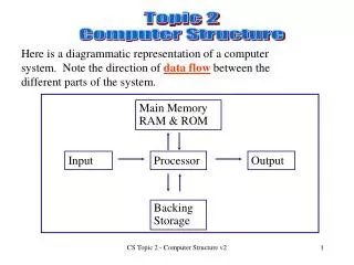
CONTROL UNIT ALU REGISTERS RAM R O M Higher Grade Computing Studies2. Computer Structure Computer Structure • The traditional diagram of a computer ... CPU OUTPUT DEVICESmonitor + printer etc. INPUT DEVICESkeyboard + mouse etc. MAIN MEMORY BACKING STORAGE
Higher Grade Computing Studies2. Computer Structure The Structure of the CPU - The Control Unit The control unit is like the CPU’s manager. The main functions of the control unit are: • To send out the signals to fetch instructions from memory. • To interpret those instructions. • To send out signals to enable instructions to be carried out. • This is known as the fetch execute cycle
Higher Grade Computing Studies2. Computer Structure The Structure of the CPU - The ALU The arithmetic and logic unit, the ALU, performs the following functions; • Calculations such as addition, subtraction, multiplication and division. • Logic functions, such as comparing values.
Higher Grade Computing Studies2. Computer Structure Main Memory • The main memory part can be visualised as a series of individual boxes with their own unique address.
Higher Grade Computing Studies2. Computer Structure The Size & Number of Memory Locations • The word length of a computer is the size of the data, in bits, which can be manipulated as a single unit by the processor. Logically, it is also the number of bits that a single memory location can store. • The size is determined by the width of the data pathways (or buses) within the computer, between the processor and the memory. • The system above has a word length of 16 bits.
Higher Grade Computing Studies2. Computer Structure Main Memory • RAM has the following features: • The CPU can write to, or read from, RAM at high speed. RAM can be changed by the CPU at any time - it is volatile. • All information stored in RAM is lost when the computer is switched off. • Static RAM holds its contents as long as there is a power supply. • Dynamic RAM (DRAM) has to be refreshed by reading and rewriting its contents frequently. • DRAM is more common because it needs less power and its circuitry is simpler.
Higher Grade Computing Studies2. Computer Structure Main Memory • ROM has the following features: • Data in ROM is permanently written into a microchip. • Data in ROM can be read by the CPU from the moment the computer is switched on. • The bootstrap loader is stored in ROM. • Data stored in ROM is not lost when the computer is turned off.
Higher Grade Computing Studies2. Computer Structure Main Memory • PROM (Programmable Read Only Memory) • Empty of data when the chip is manufactured, can be programmed by the user. Once programmed the data cannot be erased. • EPROM (Erasable PROM) • Like PROM only the chip can be removed from the computer and the program erased and another stored in its place using ultraviolet light. • EEPROM (Erasable PROM) • Like EPROM but electricity is used to erase and reprogram selected contents.
Higher Grade Computing Studies2. Computer Structure Storage Outside Main Memory • Reading /writing data to and from memory can slow down the system performance. To combat this problem, the processor can store data in cache memory or its internal registers instead of the RAM. • Cache memory • small amount of memory e.g. 512 KB. • stores the next instructions to be read. • physically closer to the processor than RAM. • uses static memory (SRAM).
Higher Grade Computing Studies2. Computer Structure Storage in the CPU - Registers • Registers are temporary storage locations in the processor. • A register can be used for tasks like ; • holding data for a calculation. • storing the address of the next instruction to be executed. • holding the instruction as it is being decoded and executed. • We will look at registers in more detail in the Fetch-Execute cycle.
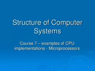
Main Memory Address 00001101 00001100 00001011 00001010 00001001 00001000 00000111 00000110 00000101 00000100 00000011 00000010 00000001 00000000 Memory Address Register Address bus Other registers 32 lines Memory Data Register Data bus 16 lines ALU Control Unit Control bus 6 lines Higher Grade Computing Studies2. Computer Structure The Processor and Main Memory Processor
Higher Grade Computing Studies2. Computer Structure Buses • A bus is an electronic highway or a collection of cables where each cable can transmit one bit. • There are three buses: • The address bus, which is used by the processor to pinpoint the memory location, needed. This is a one-way bus. • The data bus, which is used to transfer the data. Its size will usually match the word size i.e. the size of the memory locations. This is a two-way bus. • The control bus, which is used to initiate and control what is happening.
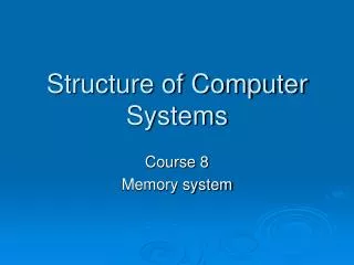
Main Memory Address 00001101 00001100 00001011 00001010 00001001 00001000 00000111 00000110 00000101 00000100 00000011 00000010 00000001 00000000 Memory Address Register Address bus Higher Grade Computing Studies2. Computer Structure The Address Bus Processor 0001000 • information is carried from the processor to the main memory • this informs the main memory which memory location • will be read or used to store data. • each wire on the bus carries one bit of information at a time. • the number of wires in this bus determines the number of memory locations. • 8 lines will allow 256 memory locations. • 32 lines will allow 68,719,476,736 memory locations. • increasing the width of this bus, increases the number of memory locations that it is possible to address.
Address Bus Address Bus • One-way. • Carries address information from CPU to Main Memory and any other devices attached to the bus. • The width of the address bus (i.e. number of wires in it) determines the number of memory locations which the CPU can address. • Every time a bit is added to the width of the address bus, the address range doubles.e.g. 2 bits = 4 addresses, 3 bits = 8 addresses etc
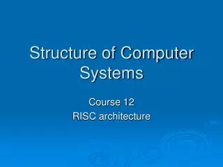
Main Memory Address 00001101 00001100 00001011 00001010 00001001 00001000 00000111 00000110 00000101 00000100 00000011 00000010 00000001 00000000 Memory Data Register Data bus Higher Grade Computing Studies2. Computer Structure The Data Bus Processor 11100101 11100101 • information is carried to and from the processor and main • memory. • this stores data in a memory location and reads data from a • memory location. • each wire on the bus carries one bit of information at a time. • the description of the computer i.e 32 bit computer, informs the user of the number of wires in this bus. • increasing the width of this bus, increases the quantity of data that can be carried at one • time and so increases the performance of the computer system.
Data Bus Two way • Carries data to and from the CPU, main memory and any other devices attached to the data bus. • The number of wires in the data bus determines the quantity of data that the data bus can carry. • More bits in the data bus means more data carried in a single operation (increased computer performance). • The size of the data bus determines the word length of a computer.
Main Memory Address 00001101 00001100 00001011 00001010 00001001 00001000 00000111 00000110 00000101 00000100 00000011 00000010 00000001 00000000 Control Unit Control bus Higher Grade Computing Studies2. Computer Structure The Control Bus Processor • each wire on the bus has its own separate function and is • activated independently of the others. Read Informs the memory that data is to be sent to the processor from a particular memory location. Write Informs the memory that data is to be stored in a particular memory location. Clock Generates a constant pulse which regulates the flow of information. A clock of 600MHz (megahertz) generates a pulse 600,000,000 times a second.
Main Memory Address 00001101 00001100 00001011 00001010 00001001 00001000 00000111 00000110 00000101 00000100 00000011 00000010 00000001 00000000 Control Unit Control bus Higher Grade Computing Studies2. Computer Structure The Control Bus Processor Interrupt This is a signal informs the processor that some important external activity has taken place. The current state of processing is saved, then the processor deals with the interrupting device, it then returns to the previous state when finished with the interrupt request. NMI The Non-Maskable Interrupt operates like an interrupt but it cannot be ignored. It must be dealt with immediately. Reset Clears all internal processor registers and returns the computer to its initial switched on state.
Control Bus • Two way • Consists of separate lines which each do a different control task • all the lines work independently. The Lines consist of:- • read line • write line • clock line • interrupt line • non-maskable interrupt line • reset line
Higher Grade Computing Studies2. Computer Structure The Links Between Processor and Memory • The Stored Program concept: • The program and data are stored in RAM until needed by the processor. • The FETCH-EXECUTE cycle: • The first instruction is fetched from memory into the processor where it is decoded and executed. The same happens to the second instruction and so on until the program ends. • The processor has to be able to pinpoint any memory location in which instructions or data are stored. Each memory location is assigned an unique address.
Higher Grade Computing Studies2. Computer Structure Read From Memory • A processor needs an instruction from memory or requires some data to perform a calculation. Here are the steps and buses needed to fetch that information from memory. 1. Processor sets up address bus with the address to be read in memory in the MAR This pinpoints the desired location 2. Processor activates the read line on the control bus This tells the memory a ‘read’ is to occur and the memory finds the requested location 3. Data from the memory is copied onto the data bus and transferred into the MDR Data is transferred to the processor
Higher Grade Computing Studies2. Computer Structure Write To Memory • Here are the steps and buses needed to write information to memory. This pinpoints the desired location 1. Processor sets up address bus with the address of the location to be written to in the MAR This prepares the data 2. Processor sets up data bus with the data to be written to memory into the MDR 3. Processor activates the write line on the control bus This tells the memory a ‘write’ is to occur and the memory finds the requested location 4. Data from the processor is copied onto the data bus and into memory Data is transferred to the memory
Steps Effect Processor sets up the address bus with the appropriate address. This pinpoints the desired location. Processor activates the read line on the control bus. This tells the location that it is to be read from. Data from the memory location is copied onto the data bus. Data is transferred to the processor. Processor deactivates all lines. Read From Memory
Steps Effect Processor sets up the address bus with the appropriate address. This pinpoints the desired location. Processor sets up the data bus with the data to be stored. Prepares the data for copying into the memory location. Processor activates the write line on the control bus. This tells the location that it is to be written to. Data is copied from the data bus into the memory location. Data is stored in memory. Processor deactivates all lines. Write to Memory
Task • Questions on p24 of booklet