Download
1 / 55
560 likes | 739 Vues
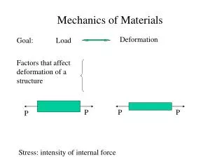
Mechanics of Materials II. UET, Taxila Lecture No. (3). Typical stress-strain curves resulting from tensile tests on some metals are shown in next Figures. Tensile test curves for various metals. Typical stress-strain curves for hard drawn wire , note the reduction in strain values.

E N D
Mechanics of Materials II UET, Taxila Lecture No. (3)
Typical stress-strain curves resulting from tensile tests on some metals are shown in next Figures
Typical stress-strain curves for hard drawn wire, note the reduction in strain values
Typical tension test results for various types of nylon and polycarbonate.
When σu & σy is not valid? In some loading cases, e.g. buckling of struts, neither the yield stress nor the ultimate strength is a realistic criterion for failure of components.
Load factor In such cases it is convenient to replace the safety factor, based on stresses, with a different factor based on loads.
Definition of load factor The load factor is therefore defined as: load at failure /allowable working load
This is particularly useful in applications of the so-called plastic limit design procedures.
Temperature stresses When the temperature of a component is increased or decreased the material Respectively expands or contracts.
If this expansion or contraction is not resisted in any way then the processes take place free of stress.
If, however, the changes In dimensions are restricted then stresses termed as Temperature stresses will be set up within the material.
Consider a bar of material with a linear coefficient of expansion ‘ ‘. Let the original length of the bar ‘L’ and let the temperature increase be t.
If the bar is free to expand the change in length would be given by L = L t Then the new length L’ will be: L’ = (L + L ) = L+ L t = L (1 + t)
Compressive thermal stresses If this extension were totally prevented, then a compressive stress would be set up equal to that produced when a bar of length: L ( 1 + t)is compressed through a distance ofL t.
In this case the bar experiences a compressive thermal strain equal to:
In most cases ‘ t’ is very small compared with unity so that:
But E = σ/ Thus σ = E = t
This is the stress set up owing to total restraint onexpansions or contractions caused by a temperature rise, or fall, t.
In the former case the stress is compressive, in the latter case the stress is tensile.
Partial Prevention If the expansion or contraction of the bar is partiallyprevented then the stress set up will be less than that given by the equation above.
Its value will be found in a similar way to that described above except that instead of being compressed through the total free expansion distance of L tit will be compressed through some proportion of this distance.
Assuming some fraction n of (L t)is allowed, then the extension which is prevented is: (1 - n) L t.
This will produce a compressive strain, as described previously, of magnitude:
The stress set up will then be: E times σ = (1-n) E t
Thus, for example, if one-third of the free expansion is prevented the stress set up will be two-thirds of that given by the equation: σ= t
Stress concentrations & stress concentration factor If a bar of uniform cross-section is subjected to an axial tensile or compressive load the stress is assumed to be uniform across the section.
However, in the presence of any sudden change of section, hole, sharp corner, notch, keyway, material flaw, etc., the local stress will rise significantly.
The ratio of this stress to the nominal stress at the section in the absence of any of these so-called stress concentrationsis termed as the stress concentration factor.
stress concentration factor SCF = Local stress/nominal stress
Toughness Toughnessis defined as: the ability of a material to withstand cracks, In other words to prevent the transfer or propagation of cracks across its section hence causing failure.
Types of toughness of materials Two distinct types of toughness mechanism exist and in each case it is appropriate to consider the crack as a very high local stress concentration.
First Toughness Type The first type of mechanism relates particularly to ductile materials which are generally regarded as tough.
This arises because the very high stresses at the end of the crack produce local yielding of the material and local plastic flow at the crack tip.
This has the action of blunting the sharp tip of the crack and hence reduces its stress concentration effect considerably (Fig. 1.15).
Area of local yielding of material reducing the stress-concentration effect
Second toughness mechanism The second mechanism refers to fibrous, reinforced or resin-based materials which have weak interfaces.
Examples for second mode of toughness Typical examples are glass-fibre reinforced materials and wood.
In the second mechanism of toughness It can be shown that a region of local tensile stress always exists at the front of a propagating crack.
Also and provided that the adhesive strength of the fibre/resin interface is relatively low (one-fifth the cohesive strength of the complete material)
Tensile stress mechanism This tensile stress opens up the interface and produces a crack sink, i.e. it blunts the crack by effectively increasing the radius at the crack tip, thereby reducing the stress-concentration effect as appears in next fig.
This principle is used stop, or at least delay, crack propagation in engineering components when a temporary "repair" is carried out by drilling a hole at the end of a crack, again reducing its stress-concentration effect.