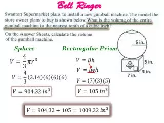
Download
1 / 51
540 likes | 779 Vues
Sphere Standards and Standard Spheres. Dr. Richard Young Optronic Laboratories, Inc. Sphere Applications. Standard Spheres Total flux measurements All the light from a lamp is measured Irradiance measurements Light at a surface is measured Sphere standards

E N D
Sphere Standards and Standard Spheres Dr. Richard Young Optronic Laboratories, Inc.
Sphere Applications • Standard Spheres • Total flux measurements • All the light from a lamp is measured • Irradiance measurements • Light at a surface is measured • Sphere standards • Large uniform source is used for calibration of instruments
Total Flux • An integrating sphere has several interesting properties: • Any part of the sphere surface “sees” all other parts of the sphere surface equally. • This means a detector at any point on the surface can measure the total power in the entire sphere. • Reflections from the sphere wall add to the lamp power, giving more power inside the sphere than the lamp is generating.
Total Flux • The lamp is placed in the center. • A baffle prevents direct light hitting the detector. • The sphere walls and baffle are highly reflective. Lamp Detector Baffle
Total Flux • Light from the lamp hits the sphere wall equally in almost all directions…
Total Flux • Light from the lamp hits the sphere wall equally in almost all directions… • But there are variations in sphere response. Shadow area Partial Shadow area
Total Flux • In these shadow areas, the “first strike” (light directly from the lamp) is not fully measured. • A sphere cannot have PERFECT response. Shadow area Partial Shadow area
Total Flux • Although perfect response is not attainable with this design, practical spheres can come very close. • How close they come depends on attention to small details of design. “An expert is someone who knows some of the worst mistakes that can be made in his subject and how to avoid them.” - W. Heisenberg
Total Flux 0.5 m sphere • Response is best viewed on a radar graph. • Response varies with sphere size and reflectivity. • If a reflectivity of 95% is used…
Total Flux 1.0 m sphere • Response is best viewed on a radar graph. • Response varies with sphere size and reflectivity. • If a reflectivity of 95% is used…
Total Flux 2.0 m sphere • Response is best viewed on a radar graph. • Response varies with sphere size and reflectivity. • If a reflectivity of 95% is used…
Total Flux • A reflectivity of 98% or more is more common for US manufactured spheres.
Total Flux • Some European standards recommend 80% reflectivity. • But this gives large geometric errors. Note the higher response in places
Total Flux • This high response is caused by reflections from the detector side of the baffle.
Total Flux • This high response is caused by reflections from the detector side of the baffle. • It is present in all spheres, but some are much worse than others.
Total Flux • All the prior sphere responses had one thing in common: • The detector had a cosine collector on it. • If we remove the cosine collector… • The response of even the best sphere is destroyed
Total Flux • Many Sources are highly directional Fluorescent Lamps
Total Flux • Many Sources are highly directional LEDs
Total Flux • A sphere has areas of uniform response (green). • And non-uniform areas (red). • If the source is highly directional, it should be pointed at a green area for the best results.
Total Flux • The green area is bigger for larger spheres. • The red area is bigger for larger baffles.
Total Flux • Geometrically, the highest accuracies are obtained by orienting lamps so the maximum output is directed at areas of uniform response. • Highly reflective coatings give much lower geometrical errors, regardless of orientation, than less reflective coatings.
Total Flux However, • Anything placed inside spheres, including lamps, holders, sockets and cables, can absorb light and change the sphere throughput. • The higher the reflectivity of the sphere, the bigger the change to throughput when something is placed inside.
Total Flux Here, the effective reflectivity is changed by just 0.25%
Total Flux • This example is for a black spherical object in the center of the sphere. • Actual changes will depend on the object’s reflectance, shape and position in the sphere, and can be larger than shown.
Total Flux • The lamp used in calibration and the lamp to be measured are rarely the same. • Different changes in throughput between these lamps will mean results will be wrong unless throughput changes are also measured.
Total Flux • An auxiliary lamp, which is housed permanently in the sphere, is used to measure changes in throughput. Auxiliary Lamp
Total Flux • The auxiliary lamp is powered up while the standard or test lamp is in the sphere. • But not switched on. • The ratio of signals is the change in throughput. • This is part of the calibration procedure. Auxiliary Lamp
Total Flux • Good total flux measurements require: • A large high reflectivity sphere. • Small, well designed, baffles. • A cosine collection detector at the sphere wall. • An auxiliary lamp.
Total Flux • It also helps to have: • Uniform measurement procedures. • e.g. keep a constant time between powering up a lamp and measuring it. • Dedicated software to guide the user through calibration and measurement. • Accurate power supplies for lamps. • NIST traceable calibration lamps. • “Heisenberg” experts for support.
Irradiance • Irradiance is the light flux falling onto a surface. • The light can come from any direction, and may be from multiple sources. • The total light hitting the surface must be measured.
Irradiance • The apparent area of a surface changes with angle. • This is called the cosine law. • A measurement device that follows the cosine law is called a cosine collector.
Irradiance • An integrating sphere with an input port makes an excellent cosine collector… • Provided certain design rules are followed.
Magnify Irradiance • The first rule is: • If light does not obey the cosine law when entering the sphere, there is little the sphere can do to compensate. • This is easier said than done because a sphere has 2 sides – the inside and the outside.
Irradiance • The first rule is: • If light does not obey the cosine law when entering the sphere, there is little the sphere can do to compensate. • This is easier said than done because a sphere has 2 sides – the inside and the outside. Outside Inside
Irradiance • This creates a “tube” effect that stops some of the light at higher angles entering the sphere directly. Some light is blocked
Irradiance • So, as the angle is changed, the cosine response gets worse and worse. A tube does not obey the cosine law A circle obeys the cosine law
Irradiance • The answer is simple. • Make the outside of the sphere flat to meet the inside at the port. Thus eliminating the “tube”.
Rule #2: add a baffle to prevent direct light hitting the detector Irradiance • So now the light enters the sphere obeying the cosine law.
Irradiance • So now the light enters the sphere obeying the cosine law. Rule #3: the detector must also obey the cosine law And the sphere can be used for irradiance measurements
Sphere Standards • If we replace the detector with a lamp, this sphere is now a source instead of a collection optic.
Sphere Standards • The uniformity of the sphere output depends on the way the light enters the sphere. • Cosine diffusers at the input give uniform output but throw away a lot of light.
Sphere Standards • It is difficult to achieve high light levels and good uniformity. • Especially if the output level also needs to be variable. • One option is to change the design.
Sphere Standards • By making sure the input light only hits the baffle, the output light is randomized. • If the input light level varies, so does the output. • To track changes we add a monitor.
Sphere Standards • This monitor is baffled so it only sees the output light, not the input. • So it can be calibrated to show the output levels directly.
Sphere Standards • The amount of light entering the sphere can be controlled by varying a slit.
Sphere Standards • Non-imaging collection mirrors can increase the light intensity. • Provided the beam is approximately uniform and over-fills the largest slit.
Sphere Standards • Slits can be linear (1D) • The width varies • Or area (2D) • The width and height vary together
Sphere Standards • A 2D slit provides better control over a wide range of levels than a linear (1D) slit. With a 1D slit, the output drops almost vertically at small slit widths
At a resolution of 10-5, the 1D slit cannot control the output below below 3 decades Sphere Standards • Expressed another way, the slit resolution needed to change the output by 1%… 2D slits are clearly superior for high dynamic range sources 2D slits can give up to 1000 times better control than 1D slits
Sphere Standards • By careful design and material selection, one can achieve: • High uniformity of output • High maximum levels of output • Very stable operation • 6 or more decades of light level adjustment • Direct reading of the output • Easy adjustability and setting to any level • An almost constant spectrum at all levels