Download
1 / 39
420 likes | 619 Vues
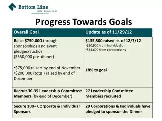
Progress Towards A High-field HTS Solenoid. Ramesh Gupta For PBL/BNL Team. Overview. High Field HTS Solenoids SBIR Fields approaching 35 to 40 T (with multiple proposals) Status (including related R&D) Focus of this presentation

E N D
Progress Towards A High-field HTS Solenoid Ramesh Gupta For PBL/BNL Team
Overview • High Field HTS Solenoids SBIR • Fields approaching 35 to 40 T (with multiple proposals) • Status (including related R&D) Focus of this presentation • 5 minute overview of HTS magnet R&D at BNL (sharing resources & experience) • Several significant programs using tens of kilometers of HTS • Summary • Note 30 T operational (Palmer, new) means ~35 T design
SBIR for High Field Solenoids Collaboration between Particle Beam Lasers (PBL) and BNL: A useful collaborative program between PBL & BNL to develop high field superconducting solenoid technology for muon collider PBL brings ideas, persons with significant experience and funding through SBIR BNL has several ongoing HTS programs with funding from a variety of sources. Synergizing various R&D allows a shot of stated goals within the limited budget permitted by individual SBIR
Overall Program Strategy There is not enough funding in one SBIR for a 35-40 T solenoid However, this could be only be done with a series of SBIR But everyone of these proposals must be attractive in its own right There are good technical and other reasons to split the program Large Loretz forces cause large integrated stresses and hence the solenoid needs to be split in several blocks anyway to manage stress accumulation Sequencing also allows lessons learnt from one SBIR to apply to the next
Components of 35-40 T Solenoid SBIR proposals from PBL: Phase II #1, 08-10 (funded): ~10 T HTS solenoid (middle) Phase II #2, 09-11 (funded): ~12 T HTS (inner) Phase 1, 11-12 (proposal under review): 12-15 T Nb3Sn (outer) 1 3 2
Overall Programmatic Features The dimensions of all solenoids have been carefully chosen so that one fits inside the other and the two HTS solenoids (generating 20+ T) fit inside the NHMFL ~19 T resistive solenoid As a part of the Phase II SBIR #2, we will test the ~20+ T HTS solenoid in the background field of NHFML ~19 T resistive magnet to test HTS technology at fields approaching 40 T Third SBIR (currently a Phase I proposal), would build a Nb3Sn solenoid with Rutherford cable and will attempt a ~35 T superconducting solenoid and demonstrate the technology Courtesy: Bob Palmer
Ambitions and Overall Challenges There are number of major challenges in 35-40 T superconducting solenoid Each SBIR takes on those challenge one at a time in a sequential manner: ~10 T HTS, 100 mm i.d. HTS solenoid: previous ~10 T HTS solenoid had ~19 mm i.d.; larger aperture =>larger stresses 20+ T all HTS solenoid with new ~12 T HTS insert together with the above this will be the highest field all HTS solenoid ever built when tested in the background field of ~19 T resistive solenoid at NHMFL, HTS will be subjected to unprecedented level of stresses 12-15 T Nb3Sn outer solenoid to first time build a ~35 T superconducting solenoid this is an attempt to make highest field superconducting solenoid ever built earlier high field Nb3Sn solenoids have been made with CICC; Rutherford cable will allow much higher current density (and hence compact size, etc.)
SBIR #1 Design, Progress and Status
HTS Solenoid SBIR #1 • Solenoid in original proposal: 10 T@4K and 5 T@33 K with 66.5 mm coil i.d. • We made this task more ambitious by increasing coil i.d. to 100 mm Under construction: Coil o.d. = ~165 mm Type of coil : Pancake No. of pancakes: 24 Conductor: 2G HTS from SuperPower ~0.1 mm X 4.2 mm 100 meter per pancake Original Proposal (Courtesy: Bob Weggel)
Conductor Received from SuperPower Each coil needs 100 meter tape. One splice allowed in 100 m for cost reasons. 350 m piece length for the price/m of 50 m Somewhat different Ic from batch to batch (spec: 100 A)
Current Status of the BNL/PBL HTS Solenoid SBIR #1 • 29 coils for 100 mm aperture solenoid have been wound with stainless steel insulation • All coils have been individually tested at 77 K (24 coils needed for the solenoid) • This is a significant size HTS R&D program with ~3 km of conductor already consumed • 24 coils have been selected after they passed all QA requirements, including 77 K test • With 2.4 km in 24 pancakes, this solenoid is made with over five times than that used in previous SuperPower solenoid • We should have the test result of completed the solenoid in about six months
“Wire Ic Coil Ic Correlation” and “New Test Setup” Correlation between 2G Coil Ic and Wire Ic at 77 K What will be the correlation at 4 K? New Test Setup
Test Results of 24 Coils at 77K Proof That A Large Number of 2G HTS Coils Can be Built and Tested without Degradation Field parallel ~0.5 T; field perpendicular ~0.3 T @40 A
SBIR #2 Design, Progress and Status
Motivation and Purpose • Muon collider solenoid will be consisted of several layers • Each of these layers can be made of different materials • Use conventional Low Temperature Superconductor (LTS) in outer layer(s) • Two options for insert: • Resistive (like that used in NHMFL solenoid in Florida) • or HTS (as LTS won’t do at 30-40 Tesla fields) • Resistive insert would consume hundreds of MW power – not practical • Development of 20+ T HTS solenoid technology is essential for a 35-40 T muon collider solenoid even while using LTS for outer layer(s)
YBCO Solenoids Bmod Bparallel • First PBL/BNL Phase II SBIR ~10+ T solenoid (i.d. = 100 mm, o.d. = 165 mm, 24 pancakes) • Second PBL/BNL Phase II SBIR ~12+ T insert (i.d. = 25 mm, o.d. = 95 mm, twelve pancakes) • Together 20+T Field Bperpendicular
Current Status of the BNL/PBL HTS Solenoid SBIR #2 (a) • Design needs twelve new pancake coils • Each will have i.d. of ~25 mm and o.d. ~95 mm • Each coil will be made with 50 meter of 100 micron thick, ~4.2 mm wide 2G HTS from SuperPower (already received) • There will not be any splice in any coil
Current Status of the BNL/PBL HTS Solenoid SBIR #2 (b) Five out of twelve coils have been wound Two coils have stainless steel insulation and three kapton insulation • A solenoid made with four coils will be taken to NHMFL for insert coil test in the background field of ~19T resistive solenoid
Upcoming Insert Coil Test at NHMFL • HTS solenoid test in background field during March 21-25, 2011 • PBL Organizer: Ron Scanlan • BNL participants: Yuko Shiroyanagi and Piyush Joshi • NHMFL point of contact: HuubWeijers • A few purpose of these tests • Compare stainless steel and kapton insulation in coils made with HTS tape • Examine coil-to-coil splice under large Lorentz forces • Examine safe operation under multiple cycles to 250 Amp (or so) • Examine influence of varying operating conditions (ramp rate, background field, etc.). Time possible for other experiments • A dry run for the 20 T HTS solenoid test (in about a year) to fields approaching 35-40 T in the same background field magnet
Significant Technical Challenges in High Field HTS Solenoids Length of conductor: Shorter length requires splices within coil (not desired). However, now available in hundreds of meters thus may need few to none. Quench protection: by far the biggest challenges - ongoing R&D to deal with it. Small imperfections in conductor that turn into significant defects under demanding conditions of high fields: need more improvement in the conductor and/or quench protection system to catch problem earlier. Anisotropic magnetic & mechanical properties: Measure and deal in the design Large stresses: Segment coils to manage stress Remember development of HTS technology is important to muon collider. We have devised an experimental R&D approach which has been very successful in many other HTS magnet programs so far. This coupled with good analysis and innovations is perhaps the best way to proceed in limited funding.
A Fly through the Support R&D to Develop Essential Technology
Variety of HTS Coils Large, small, single pancake, circular, double pancake, bi-filar
Experimental R&D with Test Coils(need to build and test many coils) Smallest coils: use 10 to 100 meters of wire (can afford to sacrifice some to understand the limit) Large coils: use ~100 meters or more wire (test proven theory)
Example: What is the Maximum Allowable Stress on the Conductor? • 2G HTS from Superpower can tolerate 700 MPaon the wide face of the tape • However, measured data is not available on narrow face in the coil. Initial guidance given were as low as 25 to 50 Mpa which would be worrisome • This is a critical number for designing a structure for high field HTS magnets BNL experimental coil On the Wide Face
BNL System for in-situ Study of the Influence of Stress on the Narrow Face
Influence of ~107 MPa Pressure on the Narrow Face of Conductor in 2G HTS Coil Load ON, Load OFF.Measure change in voltage in every ~1 m long six sections ~0.5% reversible change in Ic Answer: At least 100 MPa load may be acceptable on narrow face
Quench Protection in HTS Magnets • Quench protection of HTS coils (particularly at 4 K where current densities are high) is considered to be a major challenge in light of low quench velocities • To overcome these challenges, an advanced quench protection system with fast electronics (to detect quench fast) and low noise (to detect small resistive signal over noise). Modern data acquisition and processing system is being developed to dump energy out fast • Large number of voltage taps to detect quench in small sections • Basic system is developed and tested at 77 K • Next step: increase # of channels and test with coils at 4K • Will do extensive experimental studies with small coils
Quench Protection Studies in FRIB 2G HTS Coils and Plan in HTS Solenoid • In FRIB R&D program, 2G HTS coils were made with ~100 m of conductor from ASC and SuperPower. • Coils survived with copper current density: ~1500 A/mm2 (ASC); ~3000 A/mm2 (SuperPower) • This is too aggressive for protection and surprising that worked. In some coils, we have seen degradation/damage earlier • In HTS solenoid we will keep Cu current density ~1000 A/mm2
Other Significant ongoing HTS R&D Programs at BNL
High Temperature High Field Superconducting Magnetic Energy Storage (SMES) Options with HTS • arpa-e invited proposals on energy storage system under stimulus package • It required demonstration of certain parameters within the funding limitations • Two options for HTS: • 1. High Temperature (~65 K) Option: • Saves on cryogenics (Field ~2.5 T) • 2. High Field (~25 T) Option: • Saves on Conductor (Temp. ~4 K) • Our analysis on HTS option: • Conductor cost dominates the cryogenic cost by an order of magnitude (both in demo device and in large application • Our proposal: Bring it in play with an aggressive choice: • Go for ultra high fields 24 – 30 T : only possible with HTS
Superconducting Magnetic Energy Storage (SMES) • HTS solenoid with high energy density (E α B2) reduces the system cost • arpa-e specifically asked for “high risk high reward” proposals! • 37 were selected out of ~3,700 proposals submitted !!! • this one was the third largest in this announcement with 5.25M$ Participants: ABB, USA (Lead), SuperPower (Schenectady and Houston), and BNL (Material Science and Magnet Division) Basic structure of a single Unit Number of units in a SMES system Key Parameters: ~25 T, 100 mm, 2.5 MJ, 12 mm YBCO
Current Preliminary Design • For BNL Magnet Division, it is a follow up on the current R&D under SBIR • For MAP, it is very relevant to developing high field HTS solenoid technology • Field: ~24 T • Inner Diameter : ~100 mm • Conductor: YBCO 12 mm wide • Stored Energy: 2.5 MJ • Conductor: ~9 km (plus spare) • ~900k$ funding to magnet division, • in addition to 1M$ worth of conductor • Plus additional significant funding to improve conductor and reduce cost • Magnet needs intermediate support structure to manage stress build-up • Steve Kahn of Muons, Inc. is participating in this effort
HTS Common Coil Dipole with Bi2212 Rutherford Cable Earlier coils Earlier coils Later coils Later coils <1 kA (~2001) <1 kA (~2001) 4.3 kA (2003) 4.3 kA (2003) 4500 4500 4000 4000 Ic Ic 3500 3500 3000 3000 (4K,self field), Amps (4K,self field), Amps 2500 2500 2000 2000 1500 1500 HTS cables can carry HTS cables can carry c c I I 1000 1000 significant currents in significant currents in 500 500 magnet coils. magnets. 0 0 0 0 1 1 2 2 3 3 4 4 5 5 6 6 7 7 8 8 9 9 HTS Coil Production No. HTS Coil Production No. 8 Coils and 5 Magnets built at BNL with Rutherford Bi2212 Cable 2T Racetrack HTS coil with Bi2212
HTS Quadrupole for Facility for Rare Isotope Beams (FRIB) • Will create rare isotopes in quantities not available anywhere • Site: Michigan State University • Major source of funding for HTS magnet R&D at BNL
Significant FRIB HTS Coils 2 3 1 • FRIB coils are being made with significant HTS • Each coil uses over 1 km equivalent of standard 4 mm tape • 6 of 8 coils (4 with 2G HTS from SuperPower and 4 with ASC) are made, 3 tested at 77 K • One coil is made without any splice (average 1) • Unique opportunity to test large 2G HTS coils 4
HTS Magnet Programs at BNL BNL has been active in HTS magnet R&D for well over a decade The level of involvement may be gauged with the amount of HTS coming in. Net total in all programs (normalized to 4 mm tape): Obtained so far: ~20,000 meter Next two years (based on funded programs): ~35,000 meter Successfully designed, built and tested a large number of coils and magnets: Number of HTS coils built: ~100 Number of HTS magnet structures built and tested: ~10 HTS Magnet R&D at BNL on a wide range of operating conditions: Low B, High T (several in house, built and tested) Medium B, medium T (3 funded programs) High B, low T (>20 T, 2 funded programs) This is an order of magnitude more than in any such lab in the world
More Information for General Audience http://www.bnl.gov/magnets/staff/gupta/
Summary Significant progress towards a high field HTS solenoid with PBL/BNL SBIR 24 coils needed for outer solenoid for SBIR#1 have been successfully tested 5 of 12 coils needed for SBIR#2 have been wound Getting ready for first insert coil test at NHMFL Expect periodic results with final outcome in about a year Real shot at testing ~35 T solenoid – imagine where we would be without MAP and HTS R&D programs at BNL Magnet Division BNL has an unparalleled HTS R&D program with many significant results It may bein the interest of MAP management to have BNL magnet division directly in the overallprogramming – imagine where we would be without PBL and BNL make a great team. We are looking forward to continuing this exciting and challenging R&D and making a difference with an experimental program involving demo magnets