Download
1 / 21
210 likes | 406 Vues
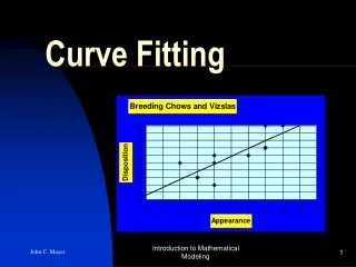
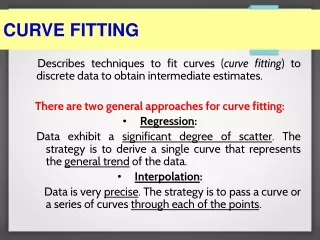
Fitting Curve Models to Edges. Most contours can be well described by combining several “round” elements (e.g., circular arcs) and “straight” elements (straight lines). First we will study a method for fitting connected straight lines to edge data.

E N D
Fitting Curve Models to Edges • Most contours can be well described by combining several “round” elements (e.g., circular arcs) and “straight” elements (straight lines). • First we will study a method for fitting connected straight lines to edge data. • Then we will discuss how to fit a circular arc to a given set of points. • Later we will apply a very general and sophisticated method (the Hough transform) for fitting straight lines to edge points. Computer Vision Lecture 11: The Hough Transform
Fitting Curve Models to Edges • Assume that you found edge data that seem to belong to one contour. • The shape of these data is somewhat non-linear, but you would like to use multiple connected straight lines (polylines) to describe the contour. • Then you can use the technique of polyline splitting. • If you have an open contour, start with a straight line connecting the two (estimated) end points. • If you have a closed contour, start with an appropriate polygon (a rectangle usually works well). Computer Vision Lecture 11: The Hough Transform
Fitting Polylines to Edges • Let us look at an example for an open contour: First, use a single straight line to connect the end points. Then find the edge point with the greatest distance from this straight line. Computer Vision Lecture 11: The Hough Transform
Fitting Polylines to Edges • Let us look at an example for an open contour: Then split the straight line in two straight lines that meet at this point. Now repeat this process with each of the two new lines. Computer Vision Lecture 11: The Hough Transform
Fitting Polylines to Edges • Let us look at an example for an open contour: Recursively repeat this process until the maximum distance of any point to the polyline falls below a certain threshold. The result is the fitting polyline. Computer Vision Lecture 11: The Hough Transform
Fitting Circular Arcs to Edges • Now we will discuss how to fit a circular arc to a set of edge points. • Consider three points p1 = (x1, y1), p2 = (x2, y2), and p3 = (x3, y3), which are pairwise different and do not lie on the same straight line. • Then we already know that there is exactly one circle that goes through all of these points. • We will now describe how to find this circle, i.e., determine its center and radius. Computer Vision Lecture 11: The Hough Transform
Fitting Circular Arcs to Edges • The points (x, y) of a circle centered at (x0, y0) and with radius r are given by the following equation: • (x – x0)2 + (y – y0)2 = r2. • To simplify the computation, we will use a coordinate system whose origin is in point p1 = (x1, y1). • In the new coordinate system we have: • x’ = x – x1 • y’ = y – y1 • (x’ – x’0)2 + (y’ – y’0)2 = r2. Computer Vision Lecture 11: The Hough Transform
Fitting Circular Arcs to Edges • Since the equation (x’ – x’0)2 + (y’ – y’0)2 = r2 is true for all points (x’, y’) on the circle, it must also apply to p1, p2, and p3. • Substituting (x’, y’) with p1, p2, and p3 gives us: • x’02 + y’02 - r2 = 0 • x’22 - 2x’2x’0 + x’02 + y’22 – 2y’2y’0 + y’02 - r2 = 0 • x’32 - 2x’3x’0 + x’02 + y’32 – 2y’3y’0 + y’02 - r2 = 0 • Subtract the first equation from the other two: • 2x’2x’0 + 2y’2y’0 =x’22 + y’22 • 2x’3x’0 + 2y’3y’0 =x’32 + y’32 Computer Vision Lecture 11: The Hough Transform
Fitting Circular Arcs to Edges • This gives us two linear equations with two unknown variables x’0 and y’0. • From these we can easily determine the center(x’0, y’0) of the circle. • The radius of the circle can then be determined by: • r2 = x’02 + y’02. • We simply add (x1, y1) to (x’0, y’0) to get the center (x0, y0) of the circle in the original coordinate system. • Then we have completely determined the circle going through points p1, p2, and p3. Computer Vision Lecture 11: The Hough Transform
Fitting Circular Arcs to Edges • In practice we usually have more than three edge points through which we want to fit a circular arc. • One possible way to do the fitting in such a case is to take the two end points of those edges as points p1 and p2. • Then we successively take every other edge point as point p2 and fit a circular arc to each generated set of points p1, p2, and p3. • In each case, we measure the deviation of the arc from all edge points. • The arc with minimum deviation is chosen as the curve model for these edges. Computer Vision Lecture 11: The Hough Transform
Hough Transform • The Hough transform is a very general technique for feature detection. • In the present context, we will use it for the detection of straight lines as contour descriptors in edge point arrays. • We could use other variants of the Hough transform to detect circular and other shapes. • We could even use it outside of computer vision, for example in data mining applications. • So understanding the Hough transform may benefit you in many situations. Computer Vision Lecture 11: The Hough Transform
Hough Transform • The Hough transform is a voting mechanism. • In general, each point in the input space votes for several combinations of parameters in the output space. • Those combinations of parameters that receive the most votes are declared the winners. • We will use the Hough transform to fit a straight line to edge position data. • To keep the description simple and consistent, let us assume that the input image is continuous and described by an x-y coordinate system. Computer Vision Lecture 11: The Hough Transform
Hough Transform • A straight line can be described by the equation: • y = mx + c • The variables x and y are the parameters of our input space, and m and c are the parameters of the output space. • For a given value (x, y) indicating the position of an edge in the input, we can determine the possible values of m and c by rewriting the above equation: • c = -xm + y • You see that this represents a straight line in m-c space, which is our output space. Computer Vision Lecture 11: The Hough Transform
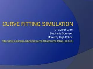
y c C C winner parameters B B A A 0 x 0 m input space output space Hough Transform • Example: Each of the three points A, B, and C on a straight line in input space are transformed into straight lines in output space. The parameters of their crossing point (which would be the winners) are the parameters of the straight line in input space. Computer Vision Lecture 11: The Hough Transform
Hough Transform • Hough Transform Algorithm: • Quantize input and output spaces appropriately. • Assume that each cell in the parameter (output) space is an accumulator (counter). Initialize all cells to zero. • For each point (x, y) in the image (input) space, increment by one each of the accumulators that satisfy the equation. • Maxima in the accumulator array correspond to the parameters of model instances. Computer Vision Lecture 11: The Hough Transform
Hough Transform • The Hough transform does not require preprocessing of edge information such as ordering, noise removal, or filling of gaps. • It simply provides an estimate of how to best fit a straight line (or other curve model) to the available edge data. • If there are multiple straight lines in the image, the Hough transform will result in multiple peaks. You can search for these peaks to find the parameters for all the corresponding straight lines. Computer Vision Lecture 11: The Hough Transform
Improved Hough Transform • Here is some practical advice for doing the Hough transform (e.g., for some future assignment). • The m-c space described on the previous slides is simple but not very practical. It cannot represent vertical lines, and the closer the orientation of a line gets to being vertical, the greater is the change in m required to turn the line significantly. • We are going to discuss an alternative output space that requires a bit more computation but avoids the problems of the m-c space. Computer Vision Lecture 11: The Hough Transform
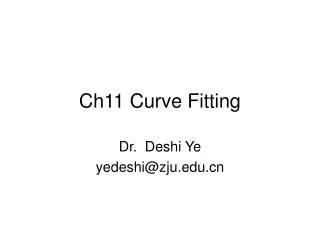
Improved Hough Transform • As we said before, it is problematic to use m (slope) and c (intercept) as an output space. • Instead, it is a good idea to use the orientation and length d of the normal of a straight line to describe it. • The normal n of a straight line l is perpendicular to l and connects l with the origin of the coordinate system. • The range of is from 0 to 360, and the range of d is from 0 to the length of the image diagonal. • Note that we can skip the interval from 180 to 270, because it would require a negative d. • Let us assume that the image is 450×450 units large. Computer Vision Lecture 11: The Hough Transform
line to be described 450 636 representation of same line in output space y d d 0 0 0 450 0 360 x input space output space Improved Hough Transform The parameters and d form the output space for our Hough transform. Computer Vision Lecture 11: The Hough Transform
Improved Hough Transform • For any edge point (x0, y0) indicated by our Sobel edge detector, we have to find all parameters and d for those straight lines that pass through (x0, y0). • We will then increase the counters in our output space located at every (, d) by the edge strength, i.e., the magnitude provided by the Sobel detector. • This way we will find out which parameters (, d) are most likely to indicate the clearest lines in the image. • But first of all, we have to discuss how to find all the parameters (, d) for a given point (x0, y0). Computer Vision Lecture 11: The Hough Transform
450 (x0, y0) y d2 d1 2 d3 1 3 0 0 450 x Improved Hough Transform By varying from 0 to 360 we can find all lines crossing (x0, y0): But how can we compute parameter d for each value of ? Idea: Rotate (x0, y0) around origin by - so that it lands on x-axis. Then the x-coordinate of the rotated point is the value of d. Computer Vision Lecture 11: The Hough Transform