Download
1 / 30
381 likes | 746 Vues
Overview of CR and DR. Gyeongsang National University Hospital Department of Diagnostic Radiology Radiation Technologist: You Dai In. Direct Radiography (DR). Overview of DR systems CCD based systems TFT + Phosphor TFT + Photoconductor. Detector technology:CCD based systems.

E N D
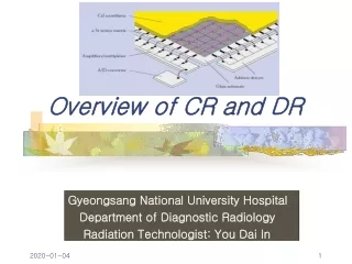
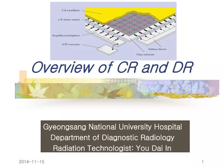
Overview of CR and DR Gyeongsang National University Hospital Department of Diagnostic Radiology Radiation Technologist: You Dai In
Direct Radiography (DR) • Overview of DR systems CCD based systems TFT + Phosphor TFT + Photoconductor
Detector technology:CCD based systems A. Lens Coupling B. Fiber optic coupling C. multiple detectors A phosphor screen converts X-rays into visual light that is projected onto a CCD or onto a CCD-array
CCD based systems • Mature technology • Mostly dedicated applications: mammography, chest • FDA approved except for mammography
Detector technology:TFT + Phosphor Phosphor screen converts X-ray photons into visual photons. Phosphor Photodiode converts visual photons into electrons Electrons are stored on capacity of switching element
TFT + Phosphor • GOS systems: available on the market • CsI systems: limited availability • FDA approved
Detector technology:TFT + Photoconductor Charge transport in photoconductor Electrons migrate to surface electrode Electrons are stored on capacity of switching element
TFT + Photoconductor Experimental except Hologics
Weaknesses of TFT systems • Low yield of TFT array fabrication • Ghost images • Charge trapping in amorphous semiconductors • Clustering of Tl+ dopant in CsI needles • Limited dynamic range (a- Se) due to high dark current • Image deformation beyond w>Nyquist due to aliassing (a-Se) • Electronic noise in low dose applications • Detector damage at high dose (capacitoroverload)
I I 0 I I 00 I I 00 I 00 I 0 I 0 I I I Principle of CR Galvanometer Photomultiplier Electrical Signal Laser Light guide A/D Storage phosphor plate Digitisation Rollers
Computed Radiography • Mature and robust technology • FDA approved and clinically accepted for all applications except mammography
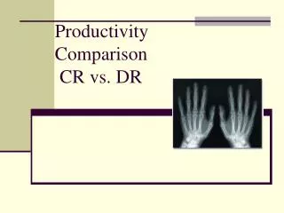
Flat Panel Investment $250-300K forone room $100K to replace damaged detectorDR 20% higher productivity 6 pat./h x 2exp./pat. x 10h/day x 200 days/yr = 24 000 exp/yr 1 room = 24 000 exp./yr Amortisation 5 yrs = 120 000 exp. $350 000 / 120 000 exp. = $2.90/exp. CR Investment $150K for 3 to 4 rooms $1K to replace damaged detectorCR productivity ~conventional 5 pat./h x 2exp./pat. x 10h/day x 200 days/yr = 20 000 exp/yr 3 rooms = 60 000 exp./yr Amortisation 5 yrs = 300 000 exp. $150 000 / 300 000 exp. = $0.50/exp. CR and DR: Economics
Assumptions • Penetration of digital acquisition in the x ray rooms will evolve from 2.5% in 1999 to 11% in 2005 • Within this digital segment, DR will substitute CR differently according to the application: • Mobile: 100% retention of CR by 2005 • Chest: 0% retention of CR • General Rad high end: 70% retention of CR • General Rad low end: 85% retention of CR
CR and DR New flat panel digital detectors are compact, offer fast image acquisition and promise excellent image quality CR DR Flat panel
Innovation in Plate technology • more absorption • higher sharpness • higher image quality “state of the art CR” Powder Phosphor BaFBr Needle Phosphor CsBr
New CsBr:Eu PhosphorHigher image quality • Cubic crystal facilitates needle growth • Equivalent specific X-ray absorption: ( =4.44 vs. 5.1 g/cm3) • Efficient stimulation with diode laser (stimulation 685 nm) • Efficient detection with PMT or CCD (emission 450 nm) • Excellent storage phosphor: • Conversion efficiency > BaFBr:Eu (more light / absorbed X-ray) • Lower stimulation energy Read-out requires 3 times less laser power
Galvo Collimator Laser Light Beam Scan-Head SHT Phosphor Image Plate Fiber Optic Phosphor ImagePlate Photo Detector Scanhead line scanner:Higher throughput Flying Spot Scanhead Scan: pixel per pixel Scan: line per line Detector: Photomultiplier Detector: CCD Fast acquisition (5s scan, 20s cycle) QE CCD > QE PMT Higher gain
Scanhead - Scanning Principles CCD Sensor Laser Diode Array CCD Sensor Optics Optics Image Plate Image Plate Laser Diode Array Front-Stimulation ADC Stratus Back-Stimulation CR Panel
CR Scanhead, the unifying technology (DR) Scanhead • simple • mature • robust • economic • multi-application Phosphor Image Plate • fast • compact • integrated • higher image quality AGFA - Patent
Conclusions • The different technologies will coexist • Best choice will depend on application • CR potential is promising • The difference between CR and DR technology will become less relevant