Download
1 / 19
1.69k likes | 7.43k Vues
Engineering Properties of Rocks. Associate Professor John Worden DEC University of Southern Qld. Engineering Properties of Rocks. At this point in your course, you should appreciate that rock properties tend to vary widely, often over short distances.

E N D
Engineering Properties of Rocks Associate Professor John Worden DEC University of Southern Qld
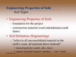
Engineering Properties of Rocks • At this point in your course, you should appreciate that rock properties tend to vary widely, often over short distances. • A corollary of this is that during Engineering practice, the penalties for geologic mistakes can be severe. • We will therefore briefly review factors that “quantise” rocks. • The study of the Engineering Properties of Rocks is termed Rock Mechanics, which is defined as follows: • “The theoretical and applied science of the mechanical behaviour of rock and rock masses in response to force fields of their physical environment.” • It is really a subdivision of “Geomechanics” which is concerned with the mechanical responses of allgeological materials, including soils.
Engineering Properties of Rocks • During Engineering planning, design and construction of works, there are many rock mechanics issues such as: • Evaluation of geological hazards; • Selection and preparation of rock materials; • Evaluation of cuttability and drillability of rock; • Analysis of rock deformations; • Analysis of rock stability; • Control of blasting procedures; • Design of support systems; • Hydraulic fracturing, and • Selection of types of structures. • For this lecture we will confine our study to thefactors that influence the deformation and failureof rocks.
Engineering Properties of Rocks • Such factors include: • Mineralogical composition and texture; • Planes of weakness; • Degree of mineral alteration; • Temperature and Pressure conditions of rock formation; • Pore water content, and • Length of time and rate of changing stress that a rock experiences. • Mineralogical Composition and Texture. • Very few rocks are homogeneous, continuous, isotropic (non directional) and elastic. • Generally, the smaller the grain size, the stronger the rock.
Engineering Properties of Rocks • Texture influences the rock strength directly through the degree of interlocking of the component grains. • Rock defects such as microfractures, grain boundaries, mineral cleavages, twinning planes and planar discontinuities influence the ultimate rock strength and may act as “surfaces of weakness” where failure occurs. • When cleavage has high or low angles with the principal stress direction, the mode of failure is mainly influenced by the cleavage. • Anisotropy is common because of preferred orientations of minerals and directional stress history. • Rocks are seldom continuous owing to pores and fissures (i.e. Sedimentary rocks). • Despite this it is possible to support engineering decisions with meaningful tests, calculations, and observations.
Engineering Properties of Rocks • Temperature and Pressure • All rock types undergo a decrease in strength with increasing temperature, and an increase in strength with increasing confining pressure. • At high confining pressures, rocks are more difficult to fracture as incipient fractures are closed. • Pore Solutions • The presence of moisture in rocks adversely affects their engineering strength. • Reduction in strength with increasing H2O content is dueto lowering of the tensile strength, which is a functionof the molecular cohesive strength of the material. • Time-dependent Behavior • Most strong rocks , like granite show little time-dependent strain or creep.
Engineering Properties of Rocks • Since there are vast ranges in the properties of rocks, Engineers rely on a number of basic measurements to describe rocks quantitatively. These are known as Index Properties. • Index Properties of Rocks: • Porosity- Identifies the relative proportions of solids & voids; • Density- a mineralogical constituents parameter; • Sonic Velocity- evaluates the degree of fissuring; • Permeability- the relative interconnection of pores; • Durability- tendency for eventual breakdown of components or structures with degradation of rockquality, and • Strength- existing competency of the rock fabric binding components.
Engineering Properties of Rocks • Porosity:Proportion of void space given by- n =p/ t , where p is the pore volume and t is the total volume. Typical values for sandstones are around 15%. In Igneous and Metamorphic rocks, a large proportion of the pore space (usually < 1-2%) occurs as planar “fissures”.With weathering this increases to > 20%. Porosity is therefore an accurate index of rock quality. • Density: Rocks exhibit a greater range in density than soils. Knowledge of the rock density is important to engineering practice. A concrete aggregate with higher than average density can mean a smaller volume of concrete required for a gravity retaining wall or dam. Expressed as weight per unit volume. • Sonic Velocity: Use longitudinal velocity Vl measured on rock core. Velocity depends on elastic properties and density,but in practice a network of fissures has an overriding effect.Can be used to estimate the degree of fissuring of a rock specimen by plotting against porosity (%).
Engineering Properties of Rocks • Permeability:As well as the degree of interconnection between pores / fissures, its variation with change in normal stress assesses the degree of fissuring of a rock. Dense rocks like granite, basalt, schist and crystalline limestone possess very low permeabilities as lab specimens, but field tests can show significant permeability due to open joints and fractures. • Durability: Exfoliation, hydration, slaking, solution, oxidation & abrasion all lower rock quality. Measured by Franklin and Chandra’s (1972) “slake durability test”. Approximately 500 g of broken rock lumps (~ 50 g each) are placed inside a rotating drum which is rotated at 20 revolutions per minute in a waterbath for 10 minutes. The drum is internally divided by asieve mesh (2mm openings) and after the 10 minutesrotation, the percentage of rock (dry weight basis) retainedin the drum yields the “slake durability index (Id)”. A sixstep ranking of the index is applied (very high-very low).
Engineering Properties of Rocks • Strength- Use Point Load Test of Broch and Franklin (1972). Irregular rock or core samples are placed between hardened steel cones and loaded until failure by development of tensile cracks parallel to the axis of loading. • IS = P/D2 , where P= load at rupture; D= distance between the point loads and I s is the point load strength. • The test is standardised on rock cores of 50mm due to the strength/size effect • Relationship between point load index (I s) and unconfined compression strength is given by: q u =24I s (50) where q u is the unconfined compressive strength, and I s (50) is the point load strength for 50 mm core. • All of the above are measured on Lab specimens, not rock masses/ outcrops, which will differ due to discontinuities at different scales.
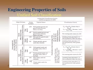
Engineering Properties of Rocks • Engineering Classification Systems for Rock: • Use of classificationsystems for rock remains controversial. • Bieniawski’s Geomechanics system uses a rock mass rating (RMR) which increases with rock quality (from 0-100). It is based on five parameters namely, rock strength; drill core quality; groundwater conditions; joint and fracture spacing, and joint characteristics. Increments from all five are summed to determine RMR. • While point load test values give rock strength, drill corequality is rated according to rock quality designation(RQD) introduced by Deere (1963). The RQD of a rockis calculated by determining the percentage of core in lengths greater than twice its diameter. • Spacing of Joints is determined from available drill core.
Engineering Properties of Rocks • It is assumed that rock masses contain three sets of joints, but the spacing of the most critical for the application is used. • Condition of joints is treated similarly. Covers the roughness and nature of coating material on joint surfaces, and should be weighted towards the smoothest and weakest joint set. • Ground water can exert a significant influence on rock mass behavior. Water inflows or joint water pressures can be used to determine the rating increment as either completely dry; moist; water under moderate pressure, or severe water problems. • Bieniawski recommended that the sum of these ratingsbe adjusted to account for favorable or unfavorable jointorientations. No points are subtracted for very favorablejoint orientations, but 12 points for unfavorable joint orientations in tunnels, and 25 points in foundations.
Engineering Properties of Rocks • Deformation and Failure of Rocks: • Four stages of deformation recognised: • Elastic; • Elastico-viscous; • Plastic, and • Rupture. • All are dependent on the elasticity, viscosity and rigidity of the rock, as well as temperature, time, pore water, anisotropy and stress history. • Elastic deformation disappears when responsible stressceases. Strain is a linear function of stress thus obeyingHooke’s law, and the constant relationship between themis referred to as Young’s modulus (E). • Rocks are non ideal solids and exhibit hysteresis during unloading.
Engineering Properties of Rocks • The elastic limit, where elastic deformation changes to plastic deformation is termed the Yield Point. Further stress induces plastic flow and the rock is permanently strained. • The first part of the plastic flow domain preserves significant elastic stress and is known as the “elastico-viscous”region. This is the field of“creep”deformation. Solids are termed “brittle”or “ductile”depending on the amount of plastic deformation they exhibit. Brittle materials display no plastic deformation. • The point where the applied stress exceeds the strength of the material is the “ultimate strength” and “rupture” results. • Young’s modulus “(E)” is the most important elasticconstant derived from the slope of the stress-strain curve.Most crystalline rocks have S-shaped stress-strain curvesthat display “hysteresis” on unloading. E varies with the magnitude of the applied stress and transient creep. • Deere and Miller (1966) identified six stress-strain types.
Engineering Properties of Rocks • Brittle Failure: • Sudden loss of cohesion across a plane that is not preceded by any appreciable permanent deformation. • For shear failure, Coulomb’s Law applies: = c + n tan , where = the shearing stress; c = the apparent cohesion; n = the normal stress and = the angle of internal friction or shearing resistance. – see diagram. • For triaxial conditions: = 0.5 ( 1 + 3) + 0.5 ( 1 - 3 ) cos 2 and, = 0.5 ( 1 - 3) sin 2 , where 1 = stress at failure , & 3 = confining pressure . • Substitution for n and in the Coulomb equation : 2c + 3 [sin 2 + tan (1- cos 2)]1= --------------------------------------------- sin 2 - tan ( 1 + cos 2)
Engineering Properties of Rocks • As 1 increases, there will be a critical plane on which the available shear strength is first reached. For this critical plane, sin 2 = cos 2, and cos 2 =sin ; so the above equation reduces to: 2c cos + 3 (1+ sin ) 1 = ---------------------------------- 1- sin • As per Coulomb’s hypothesis, an apparent value of the uniaxial tensile stress, 1 can be obtained from : 1 = 2 cos / 1 + sin , but measured values of tensile strength are generally lower than those predicted by the equation. • For rocks with linear relationships between principalstresses at rupture, there is agreement, but most rocksare non linear. Perhaps this is due to increasing frictionalgrain contact as pressure increases? • Theoretical direction of shear failure is not always inagreement with experimental observations, nor does it occur at peak strength.
Engineering Properties of Rocks • Mohr (1882) modified Coulomb’s concept. Mohr’s hypothesis states that when a rock is subjected to compressive stress, shear fracturing occurs parallel to those two equivalent planes for which shearing stress is as large as possible whilst the normal pressure is as small as possible. • Griffith (1920) claimed that minute cracks or flaws, particularly in surface layers reduced the measured tensile strengths of most brittle materials to less than those inferred from the values of their molecular cohesive forces. Although the mean stress throughout the body may be relatively low, local stresses in the vicinity of flaws were assumed to attain values equal to the theoretical strength. • Under tensile stress, stress magnification around a flaw is concentrated where the radius of curvature is smallest, ie at its end. • Concentration of stress at the ends of flaws causes themto enlarge and presumably develop into fractures.
Engineering Properties of Rocks • Brace (1964) demonstrated that fracture in hard rocks was usually initiated in grain boundaries, which can be regarded as inherent flaws under Griffith’s theory. • Subsequently Hoek (1968) determined that modified Griffith theories while adequate for prediction of fracture initiation in rocks, could not describe their propagation and subsequent failure of rocks. • Hoek and Brown (1980) reviewed published data on the strength of intact rock and developed an empirical equation (subsequently modified in 1997) that allows preliminary design calculations to be made without testing, by using an approximate rock typedependent value (m I ), and determining a value of unconfined compressive strength. • Lastly we will briefly examine the Deere and Miller (1966) classification of intact rock.
Engineering Properties of Rocks • Deere and Miller (1966) Classification of intact rock: • Any useful classification scheme should be relatively simple and based on readily measurable physical properties. • Deere and Miller based their classification on unconfined (uniaxial) compressive strength ( 1) and Young’s Modulus (E) or more specifically, the tangent modulus at 50% of the ultimate strength ratioed to the unconfined compressive strength (E/ 1 ). • Rocks are subdivided into five strength categories on a geometric progression basis; very high – high – medium –low -very low. • Three ratio intervals are employed for the modulus ratio;high – medium – low. • Rocks are therefore classed as BH (high strength- highratio); CM (medium strength – medium ratio), etc. • This data should be included with lithology descriptions and RQD values.