Download
1 / 24
240 likes | 376 Vues
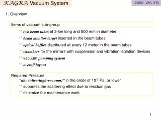
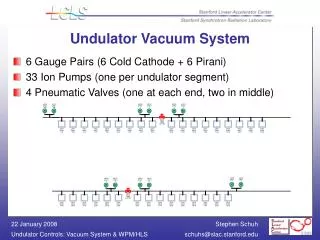
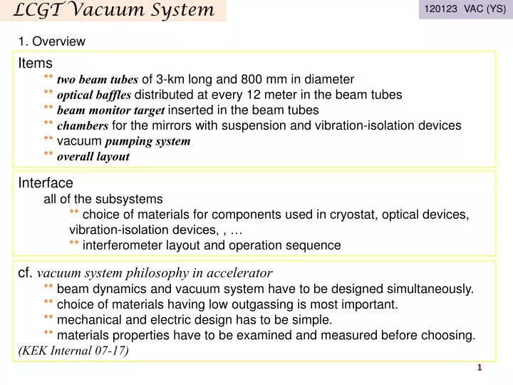
120123 VAC (YS). 1. Overview. Items ** two beam tubes of 3-km long and 800 mm in diameter ** optical baffles distributed at every 12 meter in the beam tubes ** beam monitor target inserted in the beam tubes ** chambers for the mirrors with suspension and vibration-isolation devices

E N D
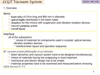
120123 VAC (YS) 1. Overview • Items • ** two beam tubes of 3-km long and 800 mm in diameter • ** optical baffles distributed at every 12 meter in the beam tubes • ** beam monitor target inserted in the beam tubes • ** chambers for the mirrors with suspension and vibration-isolation devices • ** vacuum pumping system • ** overall layout LCGT Vacuum System • Interface • all of the subsystems • ** choice of materials for components used in cryostat, optical devices, vibration-isolation devices, , … • ** interferometer layout and operation sequence • cf. vacuum system philosophy in accelerator • ** beam dynamics and vacuum system have to be designed simultaneously. • ** choice of materials having low outgassing is most important. • ** mechanical and electric design has to be simple. • ** materials properties have to be examined and measured before choosing. • (KEK Internal 07-17)
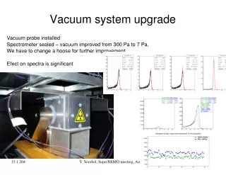
LCGT Vacuum System 120123 VAC (YS) 2. System design Required Pressure:in the order of 10-7 Pa, or lower <<scattering effect due to residual gas>> • ** We predict the noise dxdue to the residual gas (water) molecules; • for dx = 1×10-21 m/√Hz@100 Hz (safety margin of 10), • the pressure in the beam tubes is to be kept at 2×10⁻⁷ Pa. • (h=3×10-24 /(Hz)1/2 @100Hz corresponds to dx=1×10-20 m/(Hz)1/2) Penning cell Ti cathode <<minimize the maintenance work>> • ** For long-term and stable operation of the interferometer, the vacuum system is to be designed so as to minimize the maintenance work, and so as to shorten the pump-down time. A long lifetime of the vacuum component and low outgassing is required.
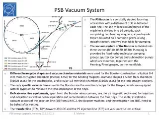
LCGT Vacuum System 120123 VAC (YS) ETMYB 2. System design ETMYA less changes “i” to “b” double chambers (2.4 and 1.5 m in dia.) //GASF + I-Pendulum + cryogenic// chambers (2 m in dia.) //stack + D-Pendulum// MC ITMY ITMX ETMXA 3000 m ETMXB MMT MCF PRM PR3 PR2 BS iLCGT iLCGT SR2 chambers (1.5 m in dia./2 m for BS) //GASF + I-Pendulum// SR3 TMP IP SRM FL P PD
LCGT Vacuum System 120123 VAC (YS) 2. System design beam tube (478 of 12-m long and 0.8 m in diameter) • ** “surface passivation” is performed by electro-polish followed by bake. • expected outgassing rate is on the order of 10-8 Pa m3 m-2 s-1, or lower. • the surface roughness is Rmax 3 mm, Ra 0.5 mm. • ** “flange connection” withmetal O-ring gasket (silver plated) is chosen. • humidity test of the gasket shows erosion proof. • ** tubes of “mirror finish by Electro-Chemical Buffing” is to be installed in the mid region of 800-m long. the surface roughness is Rmax 0.2 mm, Ra 0.03 mm. Electro-polished tube of 12 m long
LCGT Vacuum System 120123 VAC (YS) 2. System design optical baffle (every12-m along the arm, 40-mm in height, 45-degree tilted) • ** estimated scattered light noise at Kamioka • dx = 3×10-21 m/√Hz@30Hz (tube vibration amplitude=1×10-11m/√Hz assumed ) • ** For more margin, baffles at “every 12 meters”. dx = 5×10-22m/√Hz • ** For randomizing phase of edge-scattered light, baffles with “saw-tooth edge”. N=(h/d)/(L/R)
LCGT Vacuum System 120123 VAC (YS) 2. System design optical baffle (diamond-like-carbon/DLC coated) • ** measured outgassing rate of DLC is 4×10⁻⁹ Pa m3 m-2 s-1 真空
LCGT Vacuum System 120123 VAC (YS) 2. System design chambers • ** 17 of 21 chambers are operated at room temperature, 4 for cryogenic system • ** installed materials ofelastomerand plastomer should be investigated. ** Although the aluminum-coated thin PET (polyethylene terephtalate) film is suitable material for thermal shield, the outgassing rate is higher than those of metal surfaces. ** Outgassing rate of a PET film of 12 micrometer thick is measured. The rate decreases to 10-6 Pa m3 s-1 m-2 for about 10h, then reaching to the order of 10-8 Pa m3 s-1 m-2 for 200h. ** Water molecules absorbed in film is possibly diffused to the surface and desorbed with a long period of 100 hours.
LCGT Vacuum System 120123 VAC (YS) 2. System design pumping system (dry-pump and ion-pump) ** pumping unit consisted of dry-pump, TMP and ion-pump is distributed “every 100 meters” along tubes. ITMX ETMX 3000 m • ** expected pump-down scheme (a 3-km arm) • to 1 Pa >> few days by dry-pump • to 10-6 Pa >> 50 hours by TMP • to 10-7 Pa >> 500 hours by IP • (based on the ougassing rate in test tubes) TMP IP FL P DRY P • ** pumping speed of the unit (100 m) • 600 m3/h >> dry-pump • 2000 L/s >> TMP • 500 L/min >> TMP foreline pump • 1000 L/s >> IP
LCGT Vacuum System 120123 VAC (YS) control signal 0/1 2. System design pressure readout vacuum system control Center control EPICS → status: 3 ← control: 3 BA gauge ULVAC GI-M2 controller PLC Yokogawa Pirani gauge Convectron type controller Ethernet → status: 4 Gate valve (actuator) A/D Yokogawa MW100 controller ← control: 2 Ion pump VARIAN type controller → status: 2 ← control: 1 Ion pump Gamma type controller Micro IOC RS485 arm tunnel, center/end room A gate valves of large diameter takes 40 seconds for closing.
LCGT Vacuum System 120123 VAC (YS) ETMYB 2. System design layout ETMYA less changes “i” to “b” MC ITMY MMT MCF PRM PR3 PR2 BS iLCGT iLCGT ETMXB ETMXA ITMX 3000 m SR2 SR3 SRM PD
LCGT Vacuum System 120123 VAC (YS) ETMYB 2. System design layout ETMYA less changes “i” to “b” MC ITMY MMT MCF PRM PR3 PR2 BS iLCGT iLCGT ETMXB ETMXA ITMX 3000 m SR2 SR3 SRM PD
LCGT Vacuum System 120123 VAC (YS) 2. System design layout Xopt ** floors for installing chambers; horizontal optical plane of interferometer horizontal plane at X end X arm x y O (BS) horizontal plane at center room Yopt Y arm horizontal plane at Y end ETMX iLCGT BS Xopt X arm ITMX ITMY Y arm ETMY O Yopt 1/300
LCGT Vacuum System 120123 VAC (YS) 2. System design layout Xopt ** transformation matrix for 4 sets of coordinates optical plane of interferometer horizontal plane at X end X arm x y O (BS) horizontal plane at center room Yopt Y arm horizontal plane at Y end **unit vectors in each coordinate
LCGT Vacuum System 120123 VAC (YS) 2. System design layout Xopt ** transformation matrix for 4 sets of coordinates optical plane of interferometer horizontal plane at X end X arm x y O (BS) horizontal plane at center room Yopt Y arm horizontal plane at Y end **description in other coordinate
LCGT Vacuum System 120123 VAC (YS) 2. System design layout Xopt ** a set of two 1.5-km long interferometer for geophysics optical plane of interferometer horizontal plane at X end X arm x y O (BS) horizontal plane at center room Yopt Y arm horizontal plane at Y end ETMX iLCGT BS Xopt X arm ITMX ITMY Y arm ETMY O Yopt 1/300 500 m
LCGT Vacuum System 120123 VAC (UI) four coordinates
LCGT Vacuum System 120123 VAC (UI) axis Center room coordinate axis Optical coordinate axis = axis axis
LCGT Vacuum System 120123 VAC (UI) **Transformation of coordinate from Optical coordinate to Center room coordinate Center room coordinateOptical coordinate (by (Asou)
LCGT Vacuum System 120123 VAC (UI)
LCGT Vacuum System 120123 VAC (UI) **Drawing of 3D-CAD pictures
LCGT Vacuum System 120123 VAC (YS) ETMYB 3. Schedule 1) manufacturing 478 of tubes; from Apr 2011 to Mar 2013 2) manufacturing chambers; from Sep 2012 to Mar 2014 3) installing chambers in X end; Apr 2014 4) installing tubes in X arm; from Apr 2014 to Aug 2014 5) installing chambers in Center Room; Sep 2014 3) installing tubes in Y arm; from Oct 2014 to Mar 2015 5) installing chambers in Y end; Mar 2015 X arm pump down; Sep 2014 Y arm pump down; Mar 2015 expected schedule for installing (1) ETMYA Oct 2014 to Mar 2015 MC carrying tubes from MOZUMI pithead ITMY Apr 2014 MMT MCF PRM PR3 PR2 BS iLCGT iLCGT ETMXB ETMXA ITMX 3000 m SR2 SR3 Apr 2014 SRM Apr 2014 to Aug 2014 Sep 2014 PD
LCGT Vacuum System 120123 VAC (YS) ETMYB 3. Schedule • 1) manufacturing 478 of tubes; from Apr 2011 to Mar 2013 • 2) manufacturing chambers; from Sep 2012 to Mar 2014 • 3) installing chambers in X and Y ends; Apr 2014 • 4) carrying tubes and lay on the supports; • from Apr 2014 to Jun 2014 • 5) jointing tubes and pump down in X and Y arm • from Jul 2014 to Mar 2015 • 6) installing chambers in Center Room; Jul 2014 expected schedule for installing (2) ETMYA Apr 2014 carrying tubes from ATOTSU pithead Jul 2014 to Mar 2015 MC ITMY MMT MCF PRM PR3 PR2 BS Apr 2014 iLCGT iLCGT ETMXB ETMXA ITMX 3000 m SR2 SR3 Apr 2014 Jul 2014 to Mar 2015 SRM Jul 2014 PD
LCGT Vacuum System 120123 VAC (YS) 4. Risk management vacuum component failure and leakage TMP IP • ** recovery “without breaking arm-vacuum” • BA gauge failure: grid contamination, filament breakdown • feedthrough erosion; high voltage feedthrough of ion pump • power supply/controller erosion; ion pump, turbo molecular pump • durability for humidity is being examined (50°C-98%, 7 cycle of 8h-operation/98h-off). • ** recovery “by re-pumping an arm” • window (view port) break down • crack and erosion in bellow joint • metal gasket erosion • ** safety “by closing gate valves (large dia,)” • electric-power shut down • anomalous pressure rise FL P DRY P • expected pump-down scheme (a 3-km arm) • to 1 Pa >> few days by dry-pump • to 10-6 Pa >> 50 hours by TMP • to 10-7 Pa >> 500 hours by IP • (based on the ougassing rate in test tubes) ITMX ETMX 3000 m
LCGT Vacuum System 120123 VAC (YS) Appendix: outgassing data measured for technical surface • ** “surface passivation process” of stainless steel prior to installation is planned by applying electro- polishing, and then followed by pre-baking treatment. • ** “outgassing rate”of the order of 10-8 Pa m3 m-2 s-1, or lower is performed in J-PARC.