Download
1 / 24
270 likes | 408 Vues
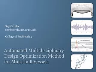
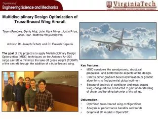
Multidisciplinary Design Optimization of Low-Airframe-Noise Transport Aircraft. Leifur Leifsson, William Mason, Joseph Schetz, and Bernard Grossman Virginia Tech and Raphael Haftka, University of Florida. Work sponsored in part by NASA Langley Research Center

E N D
Multidisciplinary Design Optimization of Low-Airframe-Noise Transport Aircraft Leifur Leifsson, William Mason, Joseph Schetz, and Bernard Grossman Virginia Tech and Raphael Haftka, University of Florida Work sponsored in part by NASA Langley Research Center Phoenix Integrations Inc. provided ModelCenter software 44th AIAA Aerospace Science Meeting and Exhibit, Reno January 9, 2006
Outline • Introduction • Research objectives • Methodology • MDO formulation • Design studies • Conclusions • Future work (Source: www.airliners.net)
Aircraft noise is a growing problem • 100% increase in noise related restrictions in the last decade • NASA’s goal is to reduce noise by 20 decibels in next 20 years Approach Noise (EPNdB) (Data from “Advisory Circular”, DOT, FAA, November 2001)
Aircraft Noise Certification Thrust Cutback Lift-Off Threshold 120 m (394 ft) Flyover 450 m (0.28 miles) Approach Sideline Brake Release 2,000 m (1.24 miles) 6,500 m (4.04 miles) • Aircraft must be certified by the FAA and ICAO in terms of noise levels • Certification noise is measured at flyover, sideline, and approach • Based on aircraft max TOGW and number of engines, the noise level is limited • Additionally, regulations limit the hours and the number of operations
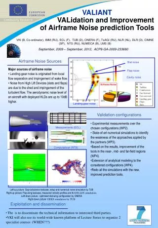
Research Objectives • Include aircraft noise in the conceptual design phase • Design low-airframe-noise transport aircraft using MDO • Quantify change in performance w.r.t. traditionally designed aircraft Airframe Noise Sources
Design Methodology: Noise as a Design Constraint Optimize aircraft without considering aircraft noise Reference configuration Aircraft noise analysis of reference configuration Reference noise level, Add a noise constraint Re-optimize the reference configuration for a target noise reduction New configuration with less noise
Optimizer MDO Framework ModelCenter Aircraft Analysis Noise Analysis • Aircraft analysis codes previously developed at Virginia Tech • High-lift system analysis module was added • ANOPP used for aircraft noise analysis • ModelCenter used to integrate the codes • DOT is the optimizer; Method of Feasible Directions optimization algorithm
ANOPP Overview • Semi-empirical code • Uses publicly available noise prediction schemes • Continuously updated by NASA • The airframe noise module is component based • Based on airframe noise models by Fink • The general approach: Far-Field Mean Square Acoustic Pressure Acoustic Power
ANOPP – Acoustic Power of Each Component • Wing Trailing-Edge (Clean wing) • Leading-Edge Slat • Increment on wing TE noise • TE noise of LE slat • Trailing-Edge Flap • Landing-Gear Turbulent BL thickness
MDO Formulation • Objective function • Min Takeoff Gross Weight • Design variables (17-22) • Geometry • Average Cruise Altitude • Sea level static thrust • Fuel weight • Constraints (16-17) • Geometry • Performance • Takeoff, Climb, Cruise, Landing • Parameters • Fuselage geometry
Planform View Section View b/ 2 c bs / 2 Slat (Es) cr V (Ef) Flap cb Aileron b c’ ct s f bf / 2 x ba / 2 d/ 2 High-Lift System Configuration (Ea) • High-lift analysis model based on semi-empirical methods by Torenbeek • Model validated by analyzing a DC-9-30 and comparing with published data
CL CLmaxlimit CLmax CLapp stall app limit = ts - gs High-Lift Design Limits and Requirements f 0 s 0 FAA Design Requirement:
MDO Formulation for the High-Lift System MDO DV’s: Constraints: Flap Deflection: Limited by ANOPP Side Constraint: Parameters:
Design Studies 1. Approach speed study 2. TE flap noise reduction 3. Airframe noise analysis of cantilever wing vs. SBW Cruise - Climb Reserve = 500 nm Mach = 0.85 Range = 7,730 nm Payload = 305 pax Climb Descent Warmup Taxi Takeoff Landing
Reducing airframe noise by reducing approach speed alone, will not provide significant noise reduction without a large weight penalty +714 sqft (+14.3%) TOGW (lb) Sref (sqft) Sref +14,240 lb (+2.4%) TOGW Approach Speed (knots) Total Airframe Noise -1.75 EPNdB LE Slat Noise (EPNdB) Main Landing Gear Nose Landing Gear TE Flap Clean Wing Approach Speed (knots)
Eliminate TE flaps by increasing Sref and a without incurring significant weight penalty a Sflap (sqft) a (deg) +5.2 deg Sflap f= 30 deg 85.6 TE Flap Noise Reduction (EPNdB) Sref TOGW (lb) +15.2% Sref (sqft) TOGW +1,900 lb 85.6 TE Flap Noise Reduction (EPNdB)
Thus, eliminating any noise associated with TE flaps Total Airframe Noise Noise (EPNdB) Main Landing Gear LE Slat TE Flap Nose Landing Gear Clean Wing TE Flap Noise Reduction (EPNdB) TE Flap Noise Reduction (EPNdB) 0 5.07 9.58 No TE Flap
Study 3: Airframe noise analysis of cantilever wing and SBW
SBW shows a significant improvement in weight & performance compared to a cantilever wing
SBW has a similar or potentially lower totalairframe noise than a cantilever wing aircraft • Main landing gear • Cantilever with 6 wheels; SBW with 4 wheels and ½ the strut length • Wing strut modeled as wing TE noise
Conclusions • A methodology for designing low-airframe-noise aircraft has been developed and implemented in an MDO framework • Reducing airframe noise by reducing approach speed alone, will not provide significant noise reduction without a large weight penalty • Therefore, more dramatic changes to the aircraft design are needed to achieve a significant airframe noise reduction • Cantilever wing aircraft can be designed with minimal TE flaps without significant penalty in weight and performance • If slat noise and landing gear noise sources were reduced (this is being pursued), the elimination of the flap will be very significant • Clean wing noise is the next ‘noise barrier’ • SBW aircraft could have a similar or potentially lower total airframe noise compared to cantilever wing aircraft
Future Work • Important topics • Effects of reduced runway length • Effects on other noise sources • Increased drag at approach => Increased engine noise for same speed • SBW’s and BWB’s should be considered in future studies • Clean wing noise model by Hosder et al.