Download
1 / 68
680 likes | 918 Vues
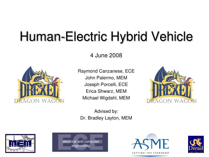
Human-Electric Hybrid Vehicle. 4 June 2008 Raymond Canzanese, ECE John Palermo, MEM Joseph Porcelli, ECE Erica Shwarz, MEM Michael Wigdahl, MEM Advised by: Dr. Bradley Layton, MEM. Overview. Problem description Vehicle overview Frame design Drive train Electrical components

E N D
Human-Electric Hybrid Vehicle 4 June 2008 Raymond Canzanese, ECE John Palermo, MEM Joseph Porcelli, ECE Erica Shwarz, MEM Michael Wigdahl, MEM Advised by: Dr. Bradley Layton, MEM
Overview • Problem description • Vehicle overview • Frame design • Drive train • Electrical components • Stability • Fairing • ASME HPVC competition • Economic analysis • Socio-environmental effects
Problem description • Urban congestion • Oil consumption (national security) • Air pollution • Obesity epidemic
Proposed Solution • people would like to cycle1, but… • weather conditions (comfort) • uncomfortable seat (comfort) • potential car encounters (safety) • limited fitness level (compatibility) • cultural barriers (social factors) 1 B. E. Layton, L. Jablonowski, R. Kirby, and N. Lampe, "Bicycle Infrastructure Development Strategy for Suburban Commuting," in ASME International Mechanical Engineering Congress and Exposition, Seattle, Washington, 2007.
Vehicle overview • weather-proof shell • minimal drag • recumbent design • 3-wheel tadpole • low center of gravity • low mass • steel roll-bar, seatbelts • 3 power sources
Performance targets • Top speed = 56 km/h (35 mph) • Acceleration = 56 km/h in 16.3 s • Braking distance = 18 m (60 ft) • Turning radius of 5.5 m (18 ft)
Component overview • Frame • Suspension • Steering • Drive train • Electrical components • Stability • Fairing
Frame design and modeling • tadpole vs. delta • back-to-back vs. front-to-back • wheelbase minimization • COG minimization
Rs Rear fork design Rh Rp • 20" fork • Spherical bearings • Damped bicycle suspension Mx = Rsx Rloading force Mx bending moment x distance from pivot a tube radius I moment of inertia sUTS failure strength smax maximum stress SF safety factor
Steering Old-20-25ft Radius New-14.5ft Radius
Steering • Additional head tube • U-joint • Central column
Drive train overview • Human component • Electrical component • Efficiency • Regenerative braking
Human performance • 100 watt constant power output • 250 watt peak power output • 200 Newton-meters (150 ft-lbs) torque output • 80 RPM cadence
Drive train design • v = 56 km/h • d = 0.5 m wheel diameter • f = 80 RPM pedaling frequency • g = gain ratio Required gain ratio of 7.35
Transmission gain ratios • jackshaft • 16t freewheel to pedals • 30t chainring to rear wheels
Motor constraints • Minimize mass • Minimize cost • Maximize human contribution • 50% at max speed • 20% during acceleration
Motor size requirement accel
Controller selection • Proportional voltage control • Human in the loop • Pulse width modulation (PWM) • Chopper control
Jackshaft Rear wheel Motor Rear pedals Front pedals
Regen in practice • 15 mile suburban commute, 5 stops • 6% energy recapture • Light urban commute • 10% energy recapture • Dense urban commute • 20% energy recapture • Clutch to engage/disengage the motor • Derailleur-free transmission
Stability • Stable at low speeds • Riders unable to lean • Rollover stability
Stability calculations 20 ft turning radius = 12 mph
Suspension mrear-end mass = 250 lbs b damping coefficient = 500 lbs·sec·in-1 k spring constant = 1000 lbs·in-1 x vertical displacement • Requirements: • Driver comfort • Stability • Lightweight • Design: • Integrated with head tubes • Bronze bearings for kingpins
Aeroshell design • “Teardrop” shape • Minimum Frontal Area • No Sharp Corners • Reduce Wake
Aeroshell testing • Elongate tail • Longer-swept underside • Compromise between drag and size
ASME HPVC competition • Madison, Wisconsin April 25-27,2008 • Events: • Design • Sprint • Utility • Endurance • Results: • Won sprint competition with top speed of 21.5 mph.