Download
1 / 29
290 likes | 314 Vues
Link-State Routing Protocols. Routing Protocols and Concepts – Chapter 10 Modified by Tony Chen. 04/01/2008. Notes:. If you see any mistake on my PowerPoint slides or if you have any questions about the materials, please feel free to email me at chento@cod.edu . Thanks! Tony Chen

E N D
Link-State Routing Protocols Routing Protocols and Concepts – Chapter 10 Modified by Tony Chen 04/01/2008
Notes: • If you see any mistake on my PowerPoint slides or if you have any questions about the materials, please feel free to email me at chento@cod.edu. Thanks! Tony Chen College of DuPage Cisco Networking Academy
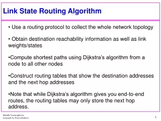
Objectives • Describe the basic features & concepts of link-state routing protocols. • Distance vector routing protocols are like road signs because routers must make preferred path decisions based on a distance or metric to a network. • Link-state routing protocols are more like a road map because they create a topological map of the network and each router uses this map to determine the shortest path to each network. • The ultimate objective is that every router receives all of the link-state information about all other routers in the routing area. With this link-state information, each router can create its own topological map of the network and independently calculate the shortest path to every network. • List the benefits and requirements of link-state routing protocols.
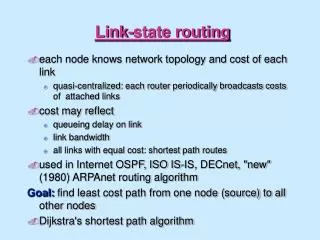
Link-State Routing • Link state routing protocols • -Also known as shortest path first algorithms -These protocols built around Dijkstra’s SPF OSPF will be discussed in Chapter 11, and IS-IS will be discussed in CCNP.
Link-State Routing • Dikjstra’s algorithm also known as the shortest path first (SPF) algorithm • This algorithm accumulates costs along each path, from source to destination.
Link-State Routing • The shortest path to a destination is not necessarily the path with the least number of hops
Link-State Routing Process • How routers using Link State Routing Protocols reach convergence • Each routers learns about its own directly connected networks • interface is in the up state • Each router is responsible for meeting its neighbors on directly connected networks • exchange hello packet to other directly connected link state routers. • Each router builds a Link-State Packet (LSP) containing the state of each directly connected link • recording all the pertinent information about each neighbor, including neighbor ID, link type, and bandwidth. • Each router floods the LSP to all neighbors, who then store all LSPs received in a database. • Each router stores a copy of each LSP received from its neighbors in a local database. • Each router uses the database to construct a complete map of the topology and computes the best path to each destination network. • The SPF algorithm is used to construct the map of the topology and to determine the best path to each network.
Link-State Routing: Step 1 – Learn about directly connected Networks • Link This is an interface on a router • Link state This is the information about the state of the links
Link-State Routing: step 2 - Sending Hello Packets to Neighbors • Link state routing protocols use a hello protocol Purpose of a hello protocol: -To discover neighbors (that use the same link state routing protocol) on its link
Link-State Routing: step 2 - Sending Hello Packets to Neighbors • Connected interfaces that are using the same link state routing protocols will exchange hello packets. • Once routers learn it has neighbors they form an adjacency • 2 adjacent neighbors will exchange hello packets • These packets will serve as a keep alive function
Link-State Routing: step 3 - Building the Link State Packet (LSP) • Contents of LSP: • State of each directly connected link • Includes information about neighbors such as neighbor ID, link type, & bandwidth. • A simplified version of the LSPs from R1 is: • 1. R1; Ethernet network 10.1.0.0/16; Cost 2 • 2. R1 -> R2; Serial point-to-point network; 10.2.0.0/16; Cost 20 • 3. R1 -> R3; Serial point-to-point network; 10.3.0.0/16; Cost 5 • 4. R1 -> R4; Serial point-to-point network; 10.4.0.0/16; Cost 20
Link-State Routing: step 4 - Flooding LSPs to Neighbors • Once LSP are created they are forwarded out to neighbors. • Each router floods its link-state information to all other link-state routers in the routing area. • Whenever a router receives an LSP from a neighboring router, it immediately sends that LSP out all other interfaces except the interface that received the LSP. • This process creates a flooding effect of LSPs from all routers throughout the routing area.
Link-State Routing: step 4 - Flooding LSPs to Neighbors • LSPs are sent out under the following conditions • Initial router start up or routing process • When there is a change in topology • including a link going down or coming up, or a neighbor adjacency being established or broken
Link-State Routing: step 5 - Constructing a link state data base • Routers use a database to construct a topology map of the network • After each router has propagated its own LSPs using the link-state flooding process, each router will then have an LSP from every link-state router in the routing area. • These LSPs are stored in the link-state database. • Each router in the routing area can now use the SPF algorithm to construct the SPF trees that you saw earlier.
Link-State Routing: step 5 - Constructing a link state data base router R1 has learned the link-state information for each router in its routing area. With a complete link-state database, R1 can now use the database and the shortest path first (SPF) algorithm to calculate the preferred path or shortest path to each network.
Link-State Routing: Example - How R1 constructs its SPF tree. • Process begins by examining R2’s LSP information • R1 can ignore the first LSP, because R1 already knows that it is connected to R2 on network 10.2.0.0/16 with a cost of 20. • R1 can use the second LSP and create a link from R2 to another router, R5, with the network 10.9.0.0/16 and a cost of 10. This information is added to the SPF tree. • Using the third LSP, R1 has learned that R2 has a network 10.5.0.0/16 with a cost of 2 and with no neighbors. This link is added to R1's SPF tree.
Link-State Routing: Example - How R1 constructs its SPF tree. • Process begins by examining R3’s LSP information • R1 can ignore the first LSP, because R1 already knows that it is connected to R3 on network 10.3.0.0/16 with a cost of 5. • R1 can use the second LSP and create a link from R3 to the router R4, with the network 10.7.0.0/16 and a cost of 10. This information is added to the SPF tree. • Using the third LSP, R1 has learned that R3 has a network 10.6.0.0/16 with a cost of 2 and with no neighbors. This link is added to R1's SPF tree.
Link-State Routing: Example - How R1 constructs its SPF tree. • Process begins by examining R4’s LSP information • R1 can ignore the first LSP because R1 already knows that it is connected to R4 on network 10.4.0.0/16 with a cost of 20. • R1 can also ignore the second LSP because SPF has already learned about the network 10.6.0.0/16 with a cost of 10 from R3. • However, R1 can use the third LSP to create a link from R4 to the router R5, with the network 10.10.0.0/16 and a cost of 10. This information is added to the SPF tree. • Using the fourth LSP, R1 learns that R4 has a network 10.8.0.0/16 with a cost of 2 and with no neighbors. This link is added to R1's SPF tree.
Link-State Routing: Example - How R1 constructs its SPF tree. • Process begins by examining R5’s LSP information • R1 can ignore the first two LSPs (for the networks 10.9.0.0/16 and 10.10.0.0/16), because SPF has already learned about these links and added them to the SPF tree. • R1 can process the third LSP learning that R5 has a network 10.11.0.0/16 with a cost of 2 and with no neighbors. This link is added to the SPF tree for R1.
Link-State Routing • Determining the shortest path • The shortest path to a destination determined by adding the costs & finding the lowest cost • Network 10.5.0.0/16 via R2 serial 0/0/0 at a cost of 22 • Network 10.6.0.0/16 via R3 serial 0/0/1 at a cost of 7 • Network 10.7.0.0/16 via R3 serial 0/0/1 at a cost of 15 • Network 10.8.0.0/16 via R3 serial 0/0/1 at a cost of 17 • Network 10.9.0.0/16 via R2 serial 0/0/0 at a cost of 30 • Network 10.10.0.0/16 via R3 serial 0/0/1 at a cost of 25 • Network 10.11.0.0/16 via R3 serial 0/0/1 at a cost of 27 Only the LANs are shown in the table, but SPF can also be used to determine the shortest path to each WAN link network.
Link-State Routing • Once the SPF algorithm has determined the shortest path routes, these routes are placed in the routing table. • The routing table will also include all directly connected networks and routes from any other sources, such as static routes. Packets will now be forwarded according to these entries in the routing table.
Link-State Routing Protocols Advantages of a Link-State Routing Protocol
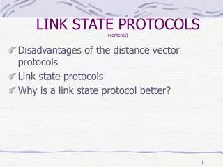
Link-State Routing Protocols • There are several advantages of link-state routing protocols compared to distance vector routing protocols. • Builds a Topological Map • Link-state routing protocols create a topological map, or SPF tree of the network topology. • Using the SPF tree, each router can independently determine the shortest path to every network. • Distance vector routing protocols do not have a topological map of the network. • Routers implementing a distance vector routing protocol only have a list of networks, which includes the cost (distance) and next-hop routers (direction) to those networks. • Fast Convergence • When receiving a Link-state Packet (LSP), link-state routing protocols immediately flood the LSP out all interfaces except for the interface from which the LSP was received. • A router using a distance vector routing protocol needs to process each routing update and update its routing table before flooding them out other interfaces, even with triggered updates. • Event-driven Updates • After the initial flooding of LSPs, link-state routing protocols only send out an LSP when there is a change in the topology. The LSP contains only the information regarding the affected link. • Unlike some distance vector routing protocols, link-state routing protocols do not send periodic updates. • Hierarchical Design • Link-state routing protocols such as OSPF and IS-IS use the concept of areas. Multiple areas create a hierarchical design to networks, allowing for better route aggregation (summarization) and the isolation of routing issues within an area.
Link-State Routing Protocols Requirements for using a link state routing protocol • Memory requirements • Typically link state routing protocols use more memory • Processing Requirements • More CPU processing is required of link state routing protocols • Bandwidth Requirements • Initial startup of link state routing protocols can consume lots of bandwidth • This should only occur during initial startup of routers, but can also be an issue on unstable networks.
Link-State Routing Protocols • Modern link-state routing protocols are designed to minimize the effects on memory, CPU, and bandwidth. • The use and configuration of multiple areas can reduce the size of the link-state databases. Multiple areas can also limit the amount of link-state information flooding in a routing domain and send LSPs only to those routers that need them. • For example, when there is a change in the topology, only those routers in the affected area receive the LSP and run the SPF algorithm. • This can help isolate an unstable link to a specific area in the routing domain. • In the figure, If a network in Area 51 goes down, the LSP with the information about this downed link is only flooded to other routers in that area. • Routers in other areas will learn that this route is down, but this will be done with a type of link-state packet that does not cause them to rerun their SPF algorithm. Note: Multiple areas with OSPF and IS-IS are discussed in CCNP
Link-State Routing Protocols • 2 link state routing protocols used for routing IP -Open Shortest Path First (OSPF) -Intermediate System-Intermediate System (IS-IS)
Summary • Link State Routing protocols are also known as Shortest Path First protocols • Summarizing the link state process -Routers 1ST learn of directly connected networks -Routers then say “hello” to neighbors -Routers then build link state packets -Routers then flood LSPs to all neighbors -Routers use LSP database to build a network topology map & calculate the best path to each destination
Summary • Link An interface on the router • Link State Information about an interface such as -IP address -Subnet mask -Type of network -Cost associated with link -Neighboring routers on the link
Summary • Link State Packets After initial flooding, additional LSP are sent out when a change in topology occurs • Examples of link state routing protocols -Open shortest path first -IS-IS