Download
1 / 30
300 likes | 306 Vues
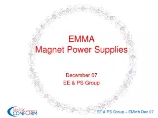
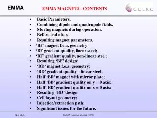
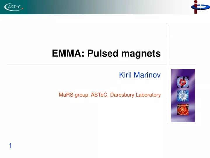
EMMA: Pulsed magnets. Kiril Marinov MaRS group, ASTeC, Daresbury Laboratory. 1. 2. Outline. Septum magnet Geometry and positioning Modelling Stray fields Field quality Kicker Delay-line vs. inductive design Modelling. 3. Septum – formulation of the problem.

E N D
EMMA: Pulsed magnets Kiril Marinov MaRS group, ASTeC, Daresbury Laboratory 1
2. Outline • Septum magnet • Geometry and positioning • Modelling • Stray fields • Field quality • Kicker • Delay-line vs. inductive design • Modelling
3. Septum – formulation of the problem • Movable septum, translation in one direction + rotation • Vacuum vessel geometry is fixed • Large bending angle – 70o extraction , 65o injection • Limited space available (w=10 cm) • The available space needs to be used efficiently. • Positioning and geometry need to be carefully optimized.
4. Septum geometry Magnetic “steel” a Coil w Eddy-current screen Determine optimum values forwand a based on “real” injection/extraction data.
Translation 5. Geometry II Rotation center Simple shape: coaxial arcs and lines
6. Hard edge model β δ α
7. Thick septum with a small aperture Incoming beam parallel to the polygon side 17.14 mm away; w=102 mm, a=35mm Advantage: c Smaller field (current): smaller stray field Disadvantages Negative rotation angle Poor beam clearance C=2.5 mm Septum wall and wing too close to the vacuum vessel
8. Thick septum with large aperture Incoming beam parallel to the polygon side 17.14 mm away; w=102 mm, a=70 mm c Negative rotation angle, bigger in absolute value; Improved clearance C≈15 mm Septum wall and wing too close to the vacuum vessel Larger pole area requires higher voltage; Using the largest possible magnet “that still fits in the box” is not the solution.
9. “Thin” septum will “small” aperture Incoming beam parallel to the polygon side 17.14 mm away; w=80mm, a=35mm Advantages: Positive rotation angle c Good beam clearance C>15 mm Longer wing can be used. Disadvantage Requires stronger field (current); stronger stray field
10. Vertical position The same incoming beam requires different “horizontal” position, rotation and magnetic field, depending on the septum “vertical” position.
11. Results • 200 injection/extraction scenarios considered for consistence with the septum geometry. • Both “phase-space painting” and “closed orbits” modes of operation Bmax=0.85 T 0<δ<7o -7 <Translation<15 mm Imax=16.5 kA L=0.19 μH Vmax=403 V
14. Field quality t=12.5 μs t=10 μs t=15 μs t=17.5 μs
15. Eddy currents distribution Eddy currents Little or no current here
16. Eddy currents distribution II Will go into the beam pipe, if necessary Beam pipe + wing “box”; extra shielding
17. Kickers Easier to design and build. Inductive magnets Kicker magnets Faster, but structurally and electrically complex. Delay-line magnets Which type is suitable for EMMA?
18. Transmission-line model of a magnet Distributed inductance L [H/m] and capacitance C[F/m]. Load impedance ZL(ω) h d Voltage source l “Magnet”
19. Transmission-line model: inductive magnet • Impedance 1) Inductive magnet • Limited to small ωl values. • Suitable for EMMA (ωl is small, fortunately…) • “Ringing” (oscillations in the trailing edge of the current pulse). • E=0, no electric field in this magnet.
20. Transmission-line model: delay-line magnet • Impedance • Impedance matching: • All frequencies “see” the same impedance: frequency independent behaviour; “high” frequency. • Travelling voltage-current wave (Z0 is real); E and B are both non-zero! • Z0 needs to be as low as possible: • E needs to be taken into account.
21. Delay-line magnet: power supply Initial voltage distribution. • An impedance-matched line (PFN) is charged to a high voltage. • A voltage-current wave is then “launched” by closing the switch.
22. Voltage evolution with time Time=1 Time=100 PFN Magnet PFN Magnet Time=400 Time=250 Magnet Magnet PFN PFN
23. Impedance • Voltage on the magnet is only a half of the source voltage. • Both forward and backward waves of equal amplitude. • Backward wave reflected upon reaching the open end of the circuit. w=58 mm, h=22 mm, D=26.5 mm Ferrite R. B. Armenta et al, PAC’05 (2005)
24. Inductive kicker: window frame design Max length 100 mm Ferrite frame Shims are important.
25. Kickers: geometry and ferrite material HV source connected here Ferrite data: Type NiZn, Bs=0.35 T; Hc=400A/m, ρ=105 Ωm, f<100 MHz (“4E2”, page 142, Ferroxcube Data Handbook 2005) Ferrite material available B max=0.07 T 70 ns current pulses! f=7 MHz
26. Kickers: magnetizing coil The shims are important. Conductor spacing. Conductor cross-section.
27. Role of the shims 0.2 % 0.2 % flux density variation in the presence of the shims.
28. Role of the shims 12 % 12 % flux density variation in the absence of the shims.
29. Vertical plane End effects White areas B< 0.065 T or B> 0.075 T Saturation